That’s good info and almost certainly means you’ll want to be on a ‘higher’ Curve than the default #9. If the house is warm when it’s cool outside but cold when it’s colder outside, that’s a clear sign of needing a higher flow temperature at lower outside temperatures, so a higher Curve number (assuming you want to prioritise comfort over running costs). Maybe try #12 instead - if you’re happy things have settled down with the changes you’ve already made.
Correct. The exact behaviour depends on exactly how the pipework is configured but in broad terms it partially separates (“buffers”) the heat pump from the UFH circuits.
Your photo shows two circulation pumps:
One at the back-left corner, partially hiding behind the DHW tank
This is presumably the heat pump’s Charge Pump, controlled by the SMO 20
Another in the middle of the photo, to the left of the buffer tank
Since this is next to the UFH manifolds this is presumably (one of) the secondary circulation pump(s), controlled by the UFH system
Out of interest, do the UFH manifolds on the other floors have their own secondary circulation pump?
Yes the buffer tank is for space heating. The red square shuttle valve (over on the far left of your photo) controls if the hot water from your heat pump goes into the hot water tank (the big white one on the left) or into the UFH heating circuits via the buffer tank (the big white one on the right). I’m not exactly sure of the purpose of the buffer tank but nearly every nibe install I’ve seen has one. @dMb will be way better at explaining this than I!
The small red and white tanks are expansion vessels. As the water in the closed system heats up it expands and these vessels allow for the expansion and change in pressure. They are very standard in heating systems including non heat pump installations.
The same as me then, not many have the 16kw and it’s a bit of a monster for running costs.
Such a big unit should heat your space (unless the heat loss calcs are massively wrong - which I doubt) so I suspect you will need to work on the optimisation and how the UFH heating control is working with the heat pump control. Fortunately you have some time before winter to get advice and thoughts from this forum so you can have (hopefully) a nice comfortable (and not too costly) winter season.
I had a similar journey when I inherited (after moving into the house) a F2040-16 unit that was very badly installed and set up. The good news is that most things can be done yourself and you hopefully don’t need the installer back.
Another thing that will be helpful to know is the exact location of your “BT25” sensor. This is measuring the temperature of the water in your space heating circuits. The SMO controller compares this BT25 temperature to the target temperature derived from the weather curve. This temperature should also be very close to the heat pump flow temperature. So understanding what all these are reading (via HA) will be key going forward. On my installation the BT25 sensor is in the top of the buffer tank in a sensor pocket. Do you have the same? (have a look under those white papers on the top of the tank). If it’s not there it should be somewhere on the pipes leaving the buffer tank and is likely connected directly into the SMO controller
I can’t really tell at the moment since #9 isn’t doing anything (which is fine with current temps). Now that I know I can update this setting if we start feeling chilly I guess I may as well wait til the autumn/winter and then try to work out the right setting for us.
Yes one per floor. One is right outside our bedroom which is a little noisier than we’d like during winter mornings so we had turned it down (although that didn’t seem to quieten it down much)
Oh oh! The installer didn’t put that in his sales pitch! I hope it can be tamed with appropriate settings!
There is a pipe coming out of the top of the buffer tank and a thin black wire going into the insulation wrapped around that pipe. Similar thin wires connect BT6/7 so that must be it.
One thing I was thinking about is whether I could collect some useful stats around how long the pump was running for heating / DHW during peak and off-peak hours. I could then draw some graphs to try and visualise when things happen during the day.
When we switched to Eon NextDrive one idea was to run the ASHP on the ground/first floors (bedrooms are on the second floor) and have it warm up those floors overnight and let that heat (partially) keep us warm during the day. I’m not convinced that all the heat won’t just disappear through the walls before we wake up. Our house is insulated where it can be but due to it’s design some of the insulation is not as thick as it may be in other houses (particularly on floors 1 & 2)
Sorry I didn’t mean it will end up that way for you. My set up is far from perfect. On cold days when the unit needs to go full steam it can consume a lot. I’ve not come across anyone with the 16kwh version yet so it would be useful to compare usage in the future and we can hopefully get into that as this thread progresses
To continue to build up a picture of your installation, how are your UFH zones controlled. Do you have thermostats in each room? Thermostats per floor? If so, are the stats currently off for summer? How any zones are controlled is key to understanding how they could adversely influence your heat pump control algorithm and subsequent usage.
This can definitely be done with the nibe data. Based on my understanding so far I would still expect your heat pump to run in heating mode on curve #9 at some point in a 24 hour day. If you’re logging data via HA we can get into determining this and go through how you can use the data to really understand what the NIBE unit is doing. Even in summer it’s possible to get a baseline idea (if you leave it in auto mode)
We have thermostats in each room. They are all hooked up to a Heatmiser hub. They aren’t explicitly set to off but the target temps are low enough that they shouldn’t be coming on much, if at all, during the summer months.
I have the myUplink integration installed on HA and I’ve also tried to save the data into InfluxDB but I’m not really sure that’s working. I’ve been viewing the data in HA history view recently. I don’t think I have the sensor that tells me whether the system is in heating or water mode so I’ve not yet figured out if I can deduce which mode it’s in and then log the start/end time it’s in each mode.
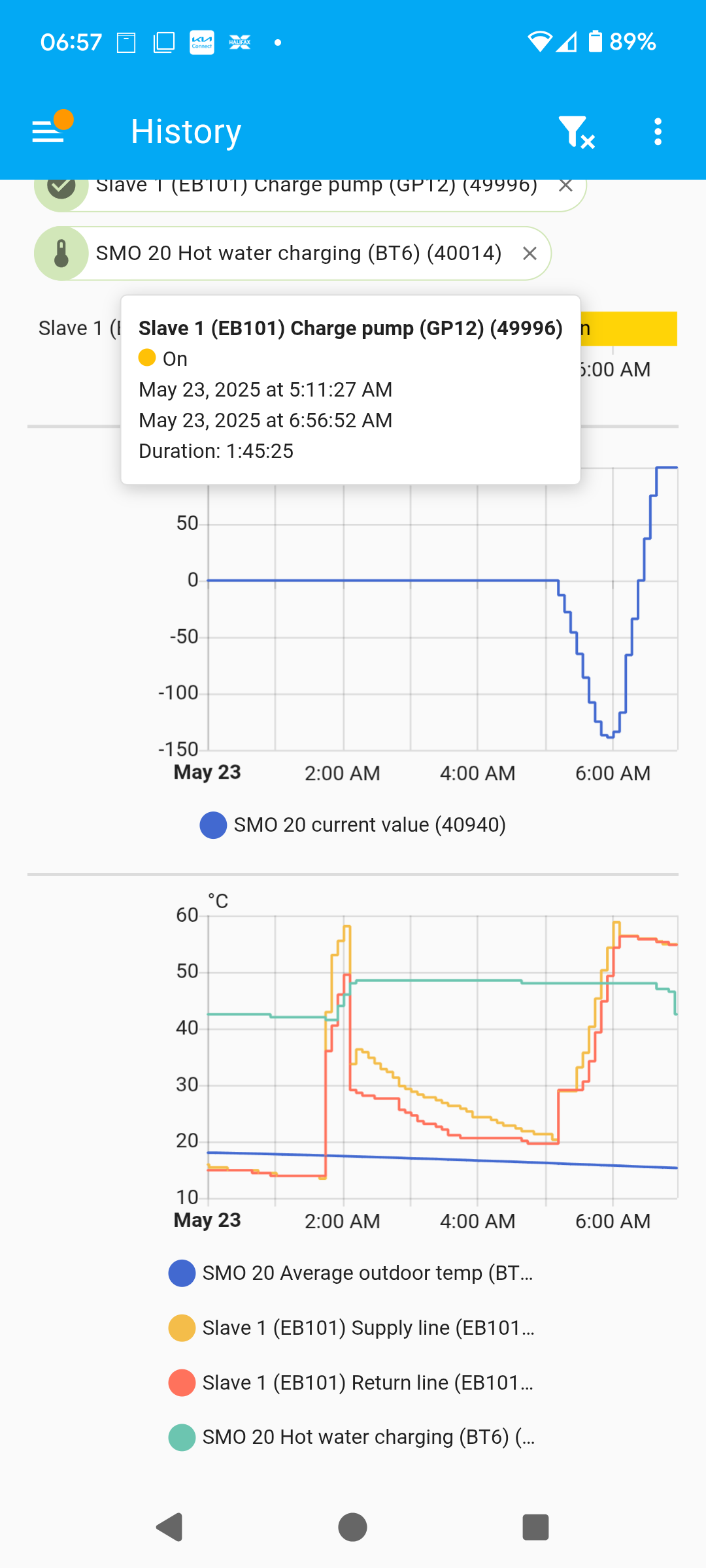
I don’t think it had all week but now that I look I see DM did briefly go negative early this morning and then move back to positive so that must have been it coming on. The charge pump running at 0511 this morning is the heating I think. I’m not sure which UFH zone would have triggered it. I’m sure I can get smarter with having the thermostat information feed into HA. I have the heatmiser integration installed but I need to do some work to organise things so that it’s easy to see what’s going on. I guess a heating focused dashboard might be the way to go but I’ll need to do some more research into the what and how. I’m sure there are plenty of YouTube videos to reference.
With NIBE systems it’s not necessary to add a third-party sensor like it is with other brands - there’s a myUplink parameter which tracks this. Unfortunately the specifics seem to vary between different NIBE models: my F1145 reports it via parameter 50095 and values like 15003 (=Off), 15004 (=Hot Water), 15005 (=Heating) but on the SMO 20 I think it’s parameter 49994. Sam will know what it is for his system; should be the same for yours.
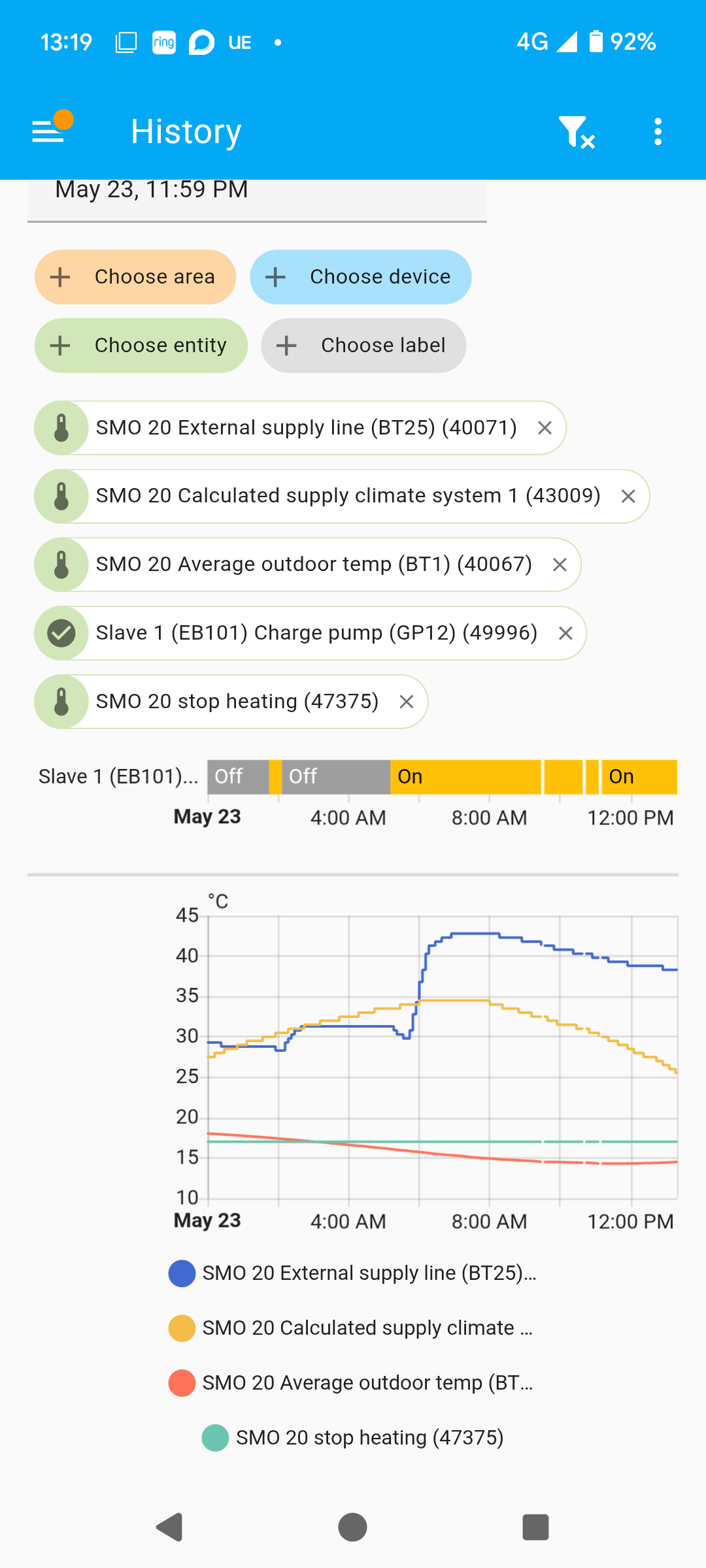
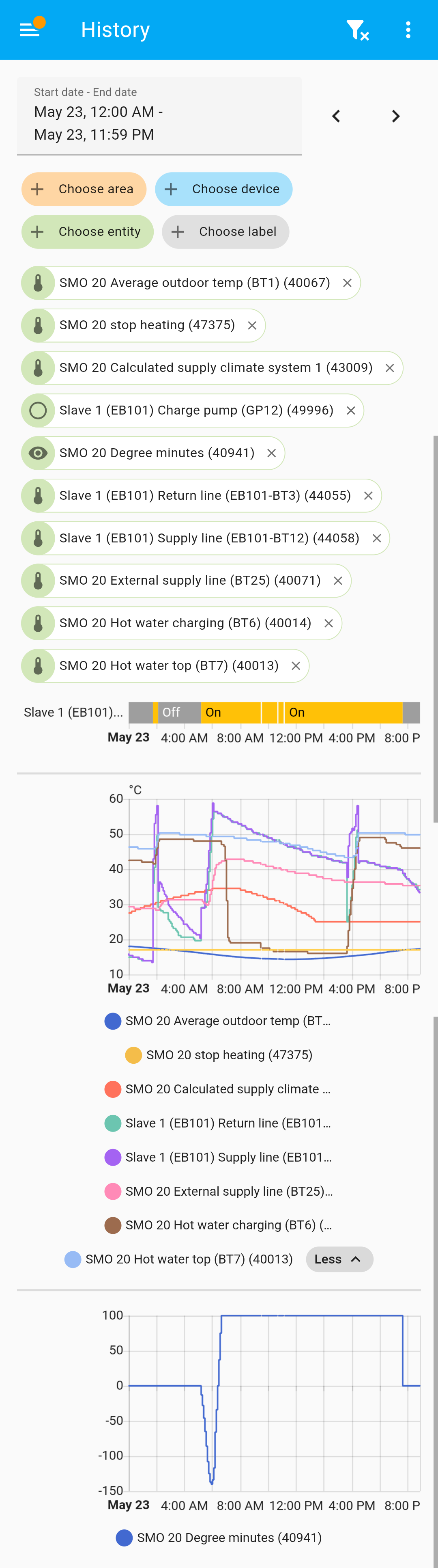
Those graphs show a Hot Water cycle around 02:00 then a Heating cycle around 06:00.
That makes sense - so those thermostats are controlling the black and white valve heads on the lower UFH manifold in your photo, based on which UFH zones want heat. I presume the UFH secondary circulation pumps run based on whether each floor wants heat or not - so at any one time you could have zero, one, two, or all three secondary circulation pumps running.
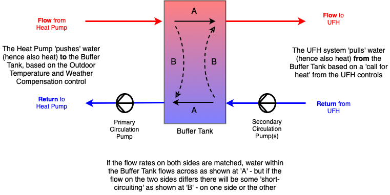
You’ll find a lot of posts elsewhere on these forums saying that Buffer Tanks are A Bad Thing. While they might not be required in small and simple installations, when there are multiple secondary circulation pumps in play it’s important to have something to hydraulically separate the ‘supply’ side (i.e. the Heat Pump) from the (highly variable) ‘demand’ side (i.e. the UFH circuits).
I’ve drawn a simple sketch to show what the Buffer Tank is trying to do - making the assumption it’s plumbed-in as a “four pipe buffer”.
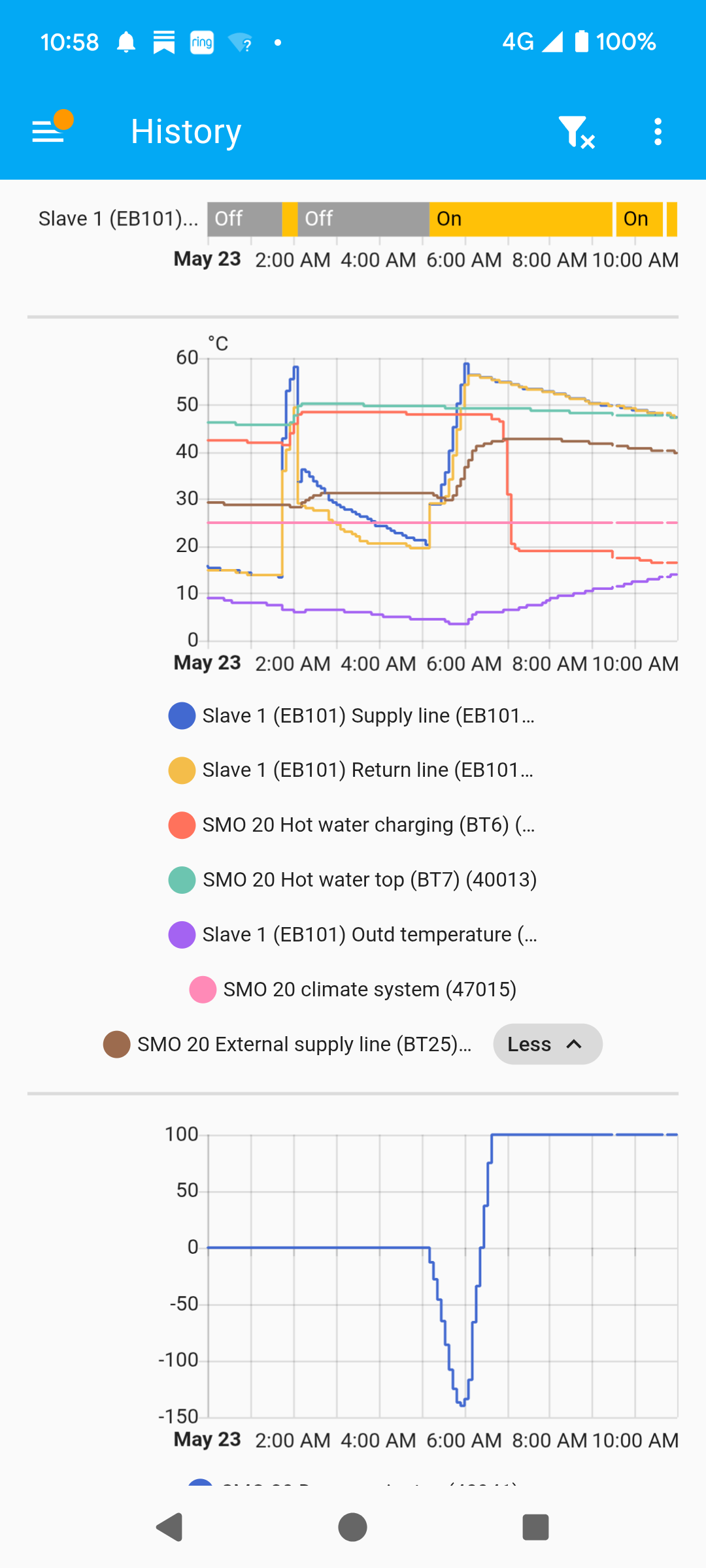
The challenge is that the controls on the ‘left’ side and the ‘right’ side aren’t linked in any way - so you get situations like at 06:00 today when the UFH didn’t want any heat but the Heat Pump ran anyway. The graph showing the slow decay of the Supply and Return Temps after 06:00 implies the primary circulation pump was just moving water to and from the Buffer Tank - and none of the secondary circulation pumps were moving any heat to the UFH.
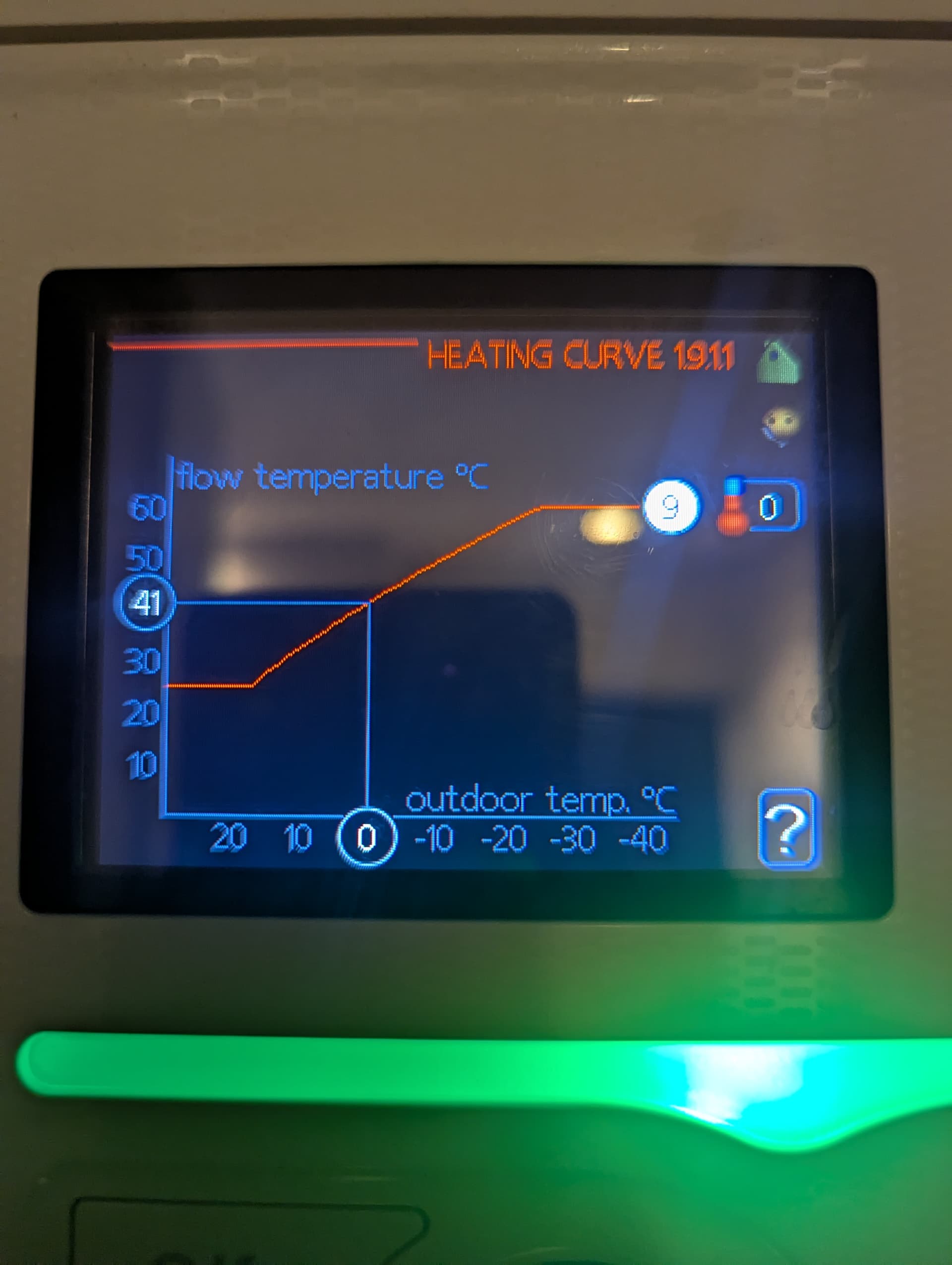
On the heating cycle, it seems odd that the flow temp gets up to 60 degrees - unless it switched to DHW. If the system is running on curve 9 and for a 15 degree (approx) outdoor temp I would expect the flow to be 35-40 degrees?
It would be really helpful if a plot can also
show S1 - target temperature and the BT25 temperature in the same graph.
I would try the priority parameter with ID 49994. Value 10 = off, 20= hot water and 30 = space heating
I’m a little confused as to what’s going on today. I’ve noticed the charge pump has been running for quite a while (and still is) which is different from recent days. Nothing particularly abnormal about our daily routines today and weather is roughly the same. I don’t see anything called S1. Maybe it’s referred to via a different name. When I’m home I could send a full list of all the things that are visible in HA of that’s helpful? I’d like to label them up with easy to understand names eventually.
Found it, it’s called the same for me. I’ve added it below. I recall you previously mentioned that the charge pump being on continuously doesn’t use much electricity and isn’t in of itself an issue, but it does seem odd that it’s decided to behave differently today so if I can uncover why it might be enlightening.
When BT25 is less than S1, the ‘DM deficit’ I wrote about before starts building up (i.e. the DM value gets increasingly negative) then once they swap over the DM value gets increasingly positive - but it’s capped at +100.
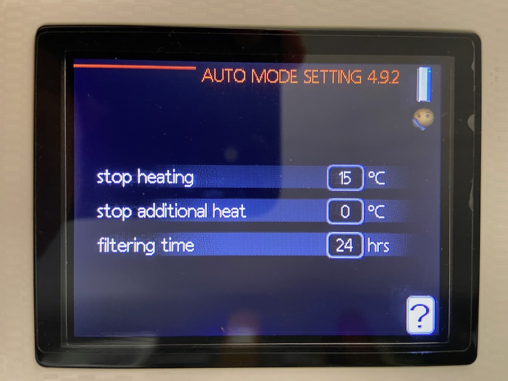
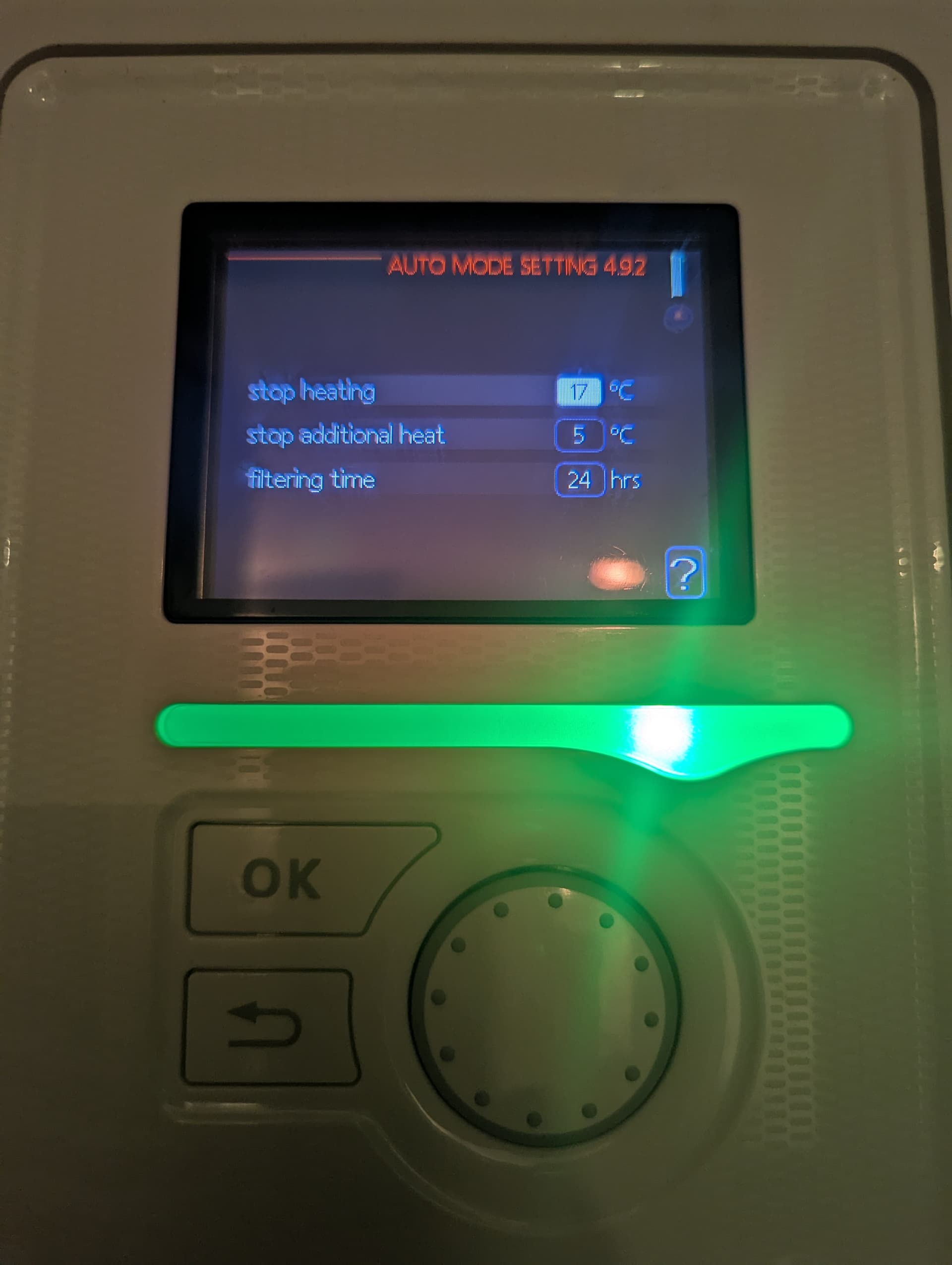
When you’re running in ‘auto’ mode, the “Auto Mode Settings” from menu 4.9.2 apply:
The help text for that screen explains that if the Outdoor Temperature - when averaged over a 24 hour period - has been above15 C (or whatever other values you have set on your system) the heating system (i.e. the charge pump) will ‘stop’. It’s been colder recently, especially overnight, hence your charge pump has been running.
I didn’t know this feature! Always something to learn
Those plots are the ones that will be helpful going forward.
The mystery still to solve is why you get a flow temperature (supply) up near 60 degrees when the target temperature (S1) is somewhere around 35 degrees. There is always an element of overshoot so it can satisfy the heating “deficit” and get the DM above 0 again, but I’ve never seen such an overshoot. This will be running the heat pump fairly hard to get to this temperature.
You also might not want such hot water in your UFH circuits, it wasn’t obvious from your first photo if there are mixing valves in the UFH manifolds.
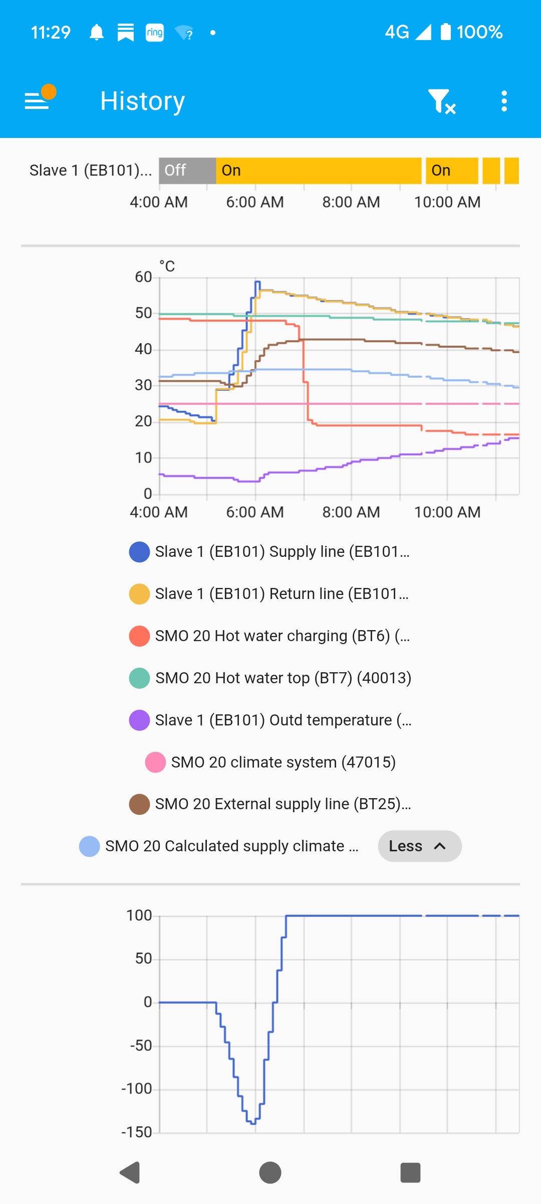
This appears to explain things accurately, assuming my settings are those defaults I’ve tidied up the graph to only show the relevant values and can see the average outdoor temp does dip below that 15°C threshold. But what does running the charge pump actually achieve if there is no heating demand at present?
Remember that the SMO 20 is not being told about any ‘call for heat’ from the Heatmiser UFH controller so it’s just doing what it’s been configured to do, based on the Outdoor Temperature and its Weather Compensation algorithm. As per my Buffer Tank sketch, the Heat Pump is ‘pushing’ heat to the buffer based on what the SMO 20 has been configured to do.
The SMO 20 is also unaware of what the ‘heat emitter’ side of your installation looks like:
It doesn’t know there are multiple secondary circulation pumps to ‘help’ with circulation
It doesn’t know whether there’s a ‘volumiser’ tank in play - which would require flow from the primary circulation pump (charge pump) in order to move heat from that volumiser into the house, between heat pump cycles
In your case it’s being overly-cautious. As I noted before, BT25 needs to see “a bit of flow” to give an accurate temperature reading - but if the charge pump is running at 30% that does seem excessive.
Got it, I keep forgetting left hand doesn’t know what right hand is doing. Seems odd that they’ve not solved that “problem”. Maybe problem is the wrong word.
Would reducing the minimum speed make sense?
Looks like its mostly been running at 30% and has kicked up a gear for a couple of short periods today. Should I think about changing the 15°C “stop temp” if we’re not actually feeling cold in the house at the moment?
That depends whether you think it’s NIBE’s problem or Heatmiser’s… so it ends up being yours . It certainly can be a (cost) problem if you’re paying for the Heat Pump to push heat to the Buffer Tank and nothing is ‘pulling’ that heat. If the heat stays in the Buffer Tank (or escapes into the house) that’s not so bad, but Sam’s experience is that a lot of heat was being lost to outside - since the charge pump is circulating water between the buffer and the outdoor unit (via any intermediate outdoor pipework).
One strategy for dealing with this lack of integration is to set all the UFH thermostats to something like 25°C, so the UFH loops are circulating water all the time and the temperature of that water is governed by the SMO 20 - the logic being that you want any heat you’ve paid for to get out into the house. That’s pretty much what I do - although I’ve got radiators in addition to limited UFH. The downside is running 4 circulation pumps all the time - and less control over how warm each room actually gets.
You mentioned you also had the Heatmiser integration for Home Assistant? Depending on what info that provides, you might have some opportunity to join the ‘left hand’ to the ‘right hand’ using Home Assistant. Something like flipping the SMO 20 from ‘manual’ to ‘auto’ mode when the UFH is calling for heat, maybe???
Probably. Would be good to get input from Sam on that - in terms of how low to go.
Good. That’s what I’d expect.
You could certainly try that but I don’t know how easy it will be to ‘dial in’ a better value (14°C? 13°C?) - or you could just go back to ‘manual’ mode for the summer.
Before you do go back to ‘manual’ mode, it would be good to get to the bottom of the point Sam flagged up that I’d not noticed - about the heating flow temperature being so high. Did you lower the curve Offset back to 0 when you switched to Curve #9? A photo of what you’re now seeing in menu 1.9.1.1 (the heating Curve) would be useful.
I realised my “stop temp” is not the default. It’s currently set to 17°C (and 5°C for stop additional heating). We’re going to be away from home for a couple of days so I’m thinking of going back to manual to save my bills but when we’re back I’d certainly like to go back to auto and figure this out properly.
Today the pump did turn off when the average temp crossed 17°C so it does look like that was the driving factor today. I note that the supply line temp heads towards 60°C during the times when the DHW is being heated (e.g. just after midnight when the off-peak period begins, again after 0630 when I got out of the shower and it was still within the off-peak period and around 1530 when it’s peak electricity but I have the water heating scheduled. My wife used the shower after 0700 so the water tank had some cold water in it when the afternoon schedule kicked in today)
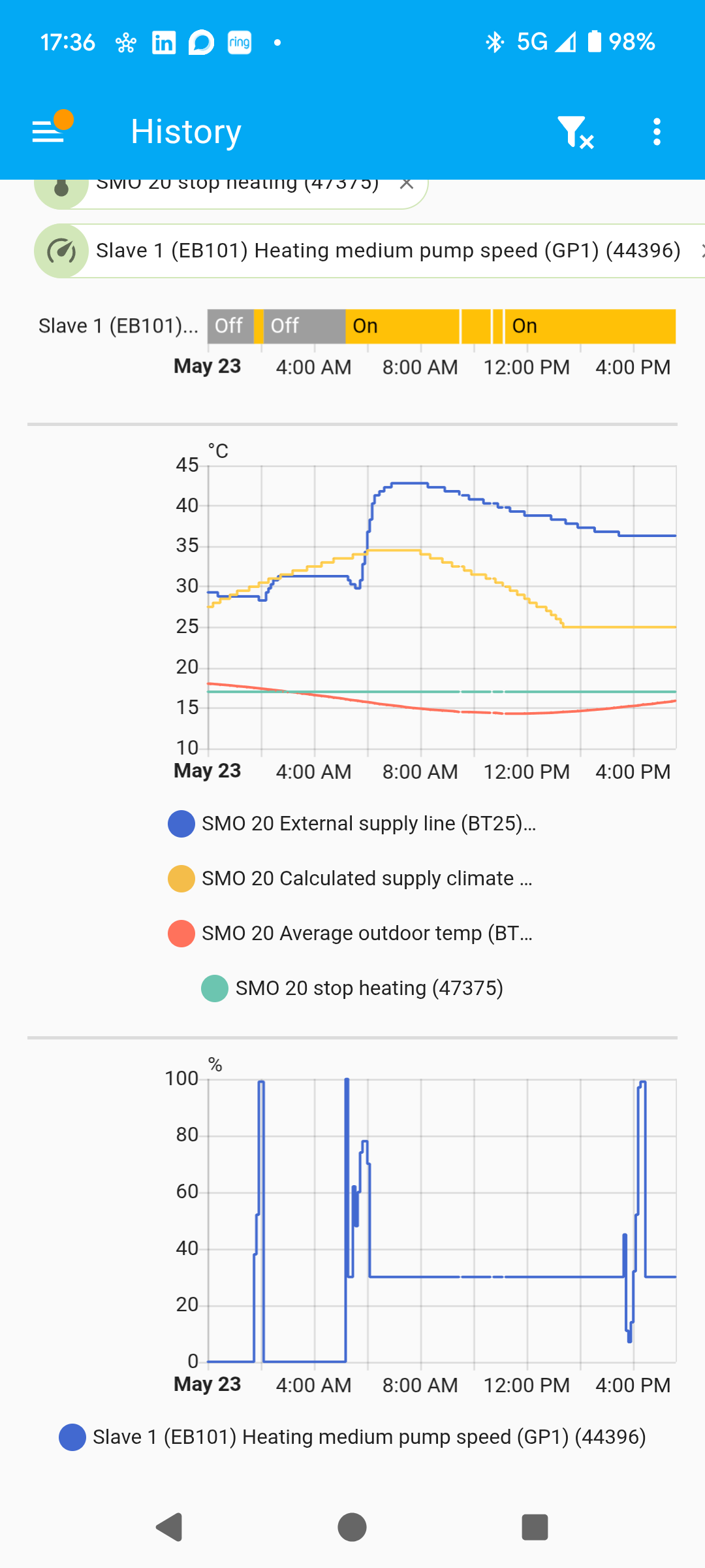
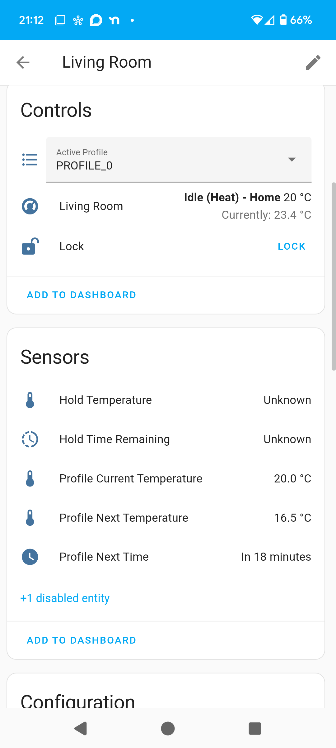
This sounds interesting. I can provide some info on what the heatmiser integration gives. Here’s a screenshot. This is the living room thermostat. Note that the wire that reads the temperature is embedded in the floor so it’s important to note that the 23.4°C current temperature shown here is certainly not the temperature of the room. The profile (i.e. target) is set to 20°C right now so given the floor is supposedly above that it’s not calling for heat. We have a profile so at some point later this evening the target will drop to 16.5°C. I think we probably need to do a bit more tinkering to work out which floor temp equates to a comfortable air temp in each room. I think there is certainly scope to make one or more room(s) on each floor draw heat and so activate the pump if that’s worth trying.
No such metric on my side and I don’t see anything obvious. From what I can see I’d have to deduce what the system is trying to do by combining multiple sensors with some logic. HA should be flexible enough to do it but it does seem a little more complicated than I was hoping for.