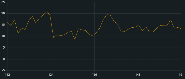
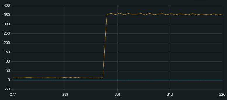
I downloaded EmonLib library and tested my circuit with the current_only sample program. When The heater is Off or diconnected, I have a small fluctuating value and when I switch it On, a new value but not the real current consumption (see graph)
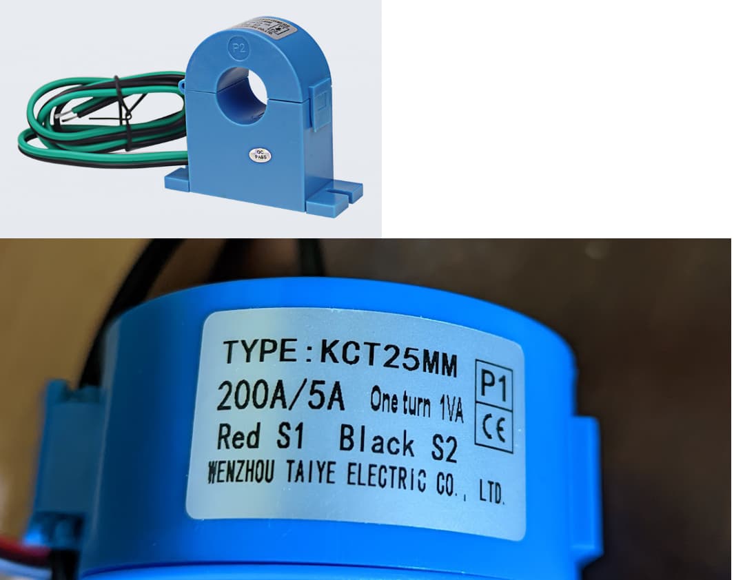
I am not at all surprised that you cannot read sensible values. Your c.t has a 5 A output, and you have NO burden resistor. The c.t. will be attempting to drive 5 A into the ESP analogue input, and it will try to generate as high a voltage as necessary (subject to the insulation breaking down) to achieve that. It is very likely that you have damaged or destroyed the input to the ESP32.
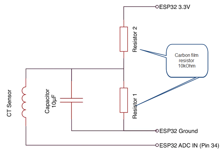
What you should have done is provide a burden resistor, which you connect directly across the secondary winding of the c.t., so that, at the rated current of the c.t. (200 A in the primary circuit, 5 A in the secondary winding, the current flowing in the burden will give a peak to peak voltage that is close to but less (around 5 - 10% less) than the input voltage span of the ESP32.
For example, if you want 1 V peak-peak to send to the ESP 32, that equates to about 300 mV rms. To develop 300 mV with 5 A flowing, the resistor value would be 0.06 Ω, and the power rating would be at least 1.5 W, a 3 W resistor would be appropriate.
I’m in the US, so am on the same type of grid you are.
200 Amp service is quite oftem very misunderstood. More info here:
Your 18 kW heater draws ~75 Amps, so you might be better served by a 100A:333mV CT.
(150A:333mV CTs are also available) The downside is finding one with a large enough wire-window to accommodate your Service Entrance Wires.
You would need to have one manufactured, or make one yourself - use a strip of metal whose resistivity you know, ideally having a low temperature coefficient (of resistance), and calculate the size to give the resistance value you need.
Or to put it another way, start with a more appropriate c.t., as Bill infers. That 5 A c.t. is intended to drive a 5 A moving iron meter, scaled 0 - 200 A; it’s not a good choice for an electronic instrument.