Our ashp has just been installed. It is a Mitsubishi Ecodan. Is there any way I can get the flow rate from the installed hardware?
The heatpump monitoring seems to suggest that I need to have had a flow meter installed. This is now rather difficult to do now the system is commissioned and filled with anti-freeze.
Some Ecodan installations include a flow meter. Do you know if your ecodan display provides information on heat output and COP? There is a service menu from which you can request system temperatures etc and if you have a flow meter installed already you might be able to find the flow rate that way
You can get a good estimate of flow rate if you know the exact kW heat output from the heat pump software and the delta-t (difference in flow and return temperature). As we know the specific heat capacity of water you can get a reasonable estimate of the flow. The systems I work on (different manufacturer, so can’t say for Ecodan) use this method to give a good indication of flow rates. Note, this method might be slightly off with inhibitor or glycol added for antifreeze protection as that changes the specific heat capacity and increases the “gloopiness” of the water, for want of a better term. Examples here:
Note I have no idea how well this would integrate into OEM / heat pump monitor. Looks like this sensor has different options for output signalling too. Adding an inline sensor may also act as a flow restriction, so it might actually be better off not having it in circuit!
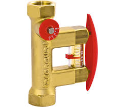
There is also another device useful for checking flow rates manually that can be installed, made by Taconova, either the Tacosetter:
with the restrictor opened fully for max flow or the TacoControl flow meter. With this, they are always in circuit (potentially adding a restriction to the system!) and require you to walk up and squeeze the red lever and read off the bottom of the float.
Just as a “rough n ready” rule of thumb, look at the difference between flow and return temperatures and ideally the difference between them in heating should be between 5k to 8k difference (5 to 8 degrees C difference). Too high a difference and that suggests poor flow rates. Good flow rates usually result in a happy heat pump
It’s not something I’d advise, Id be worried that the combination might effect the reading (e.g pull the voltage output lower) and if the Ecodan is using the reading for its control algorithm that could cause problems.
Yes having to drain down the system to install a flow meter is a pain and expense!
Thank you for the reply. Draining the system to add another flow meter is really what I was hoping to avoid! The system has 25l of anti-free in it, which is not straiught forward to refill.
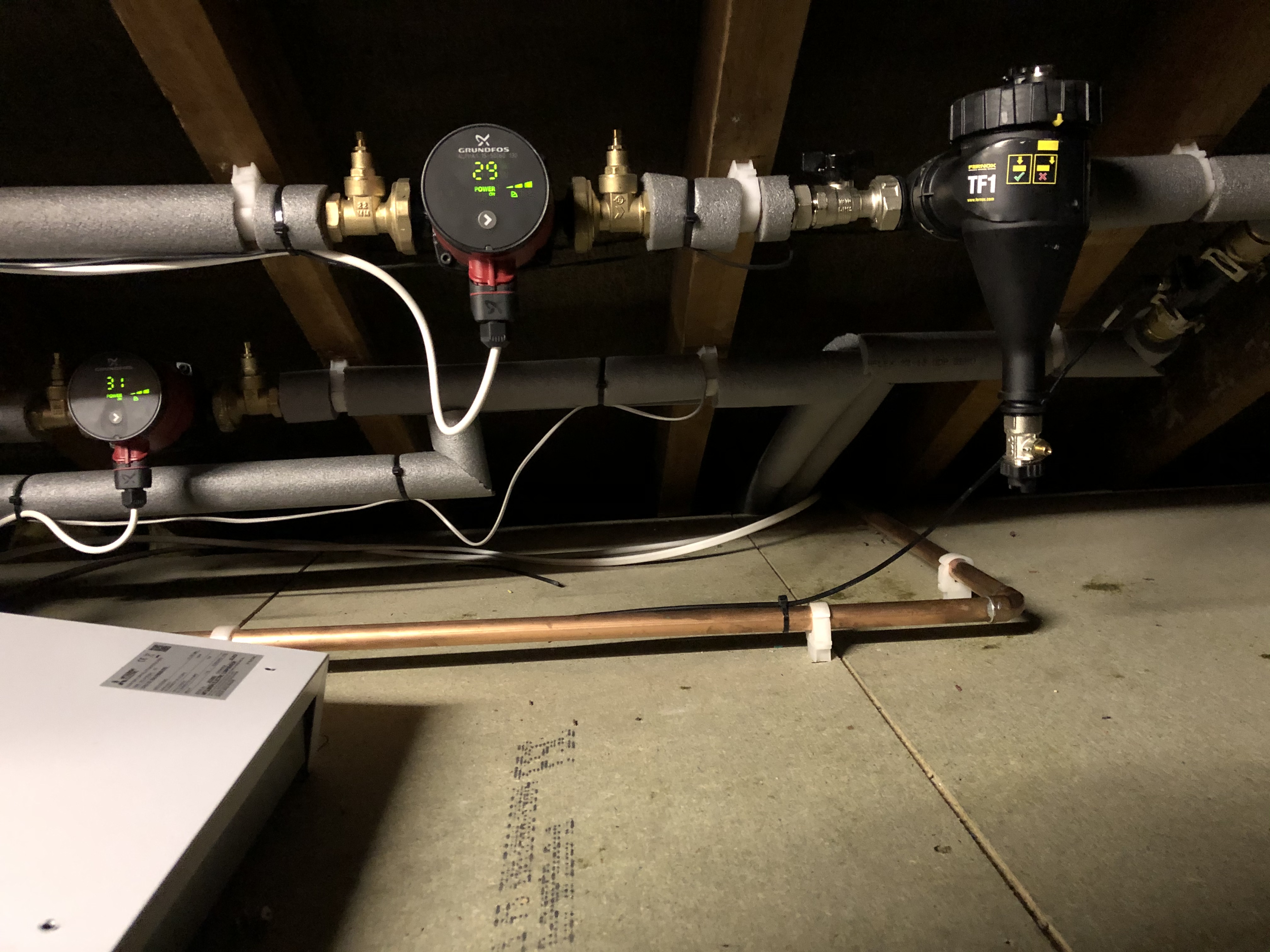
I guess, I could remove one of the central heating pumps and refit the pump inline with a flow meter and a coupld of extra bends of pipe? That would avoid me draining the system.
Looking at the pipework I can remove the section with a pump and the filter, and a few bends then insert a flow meter between the filter and pump, then refit the them back.
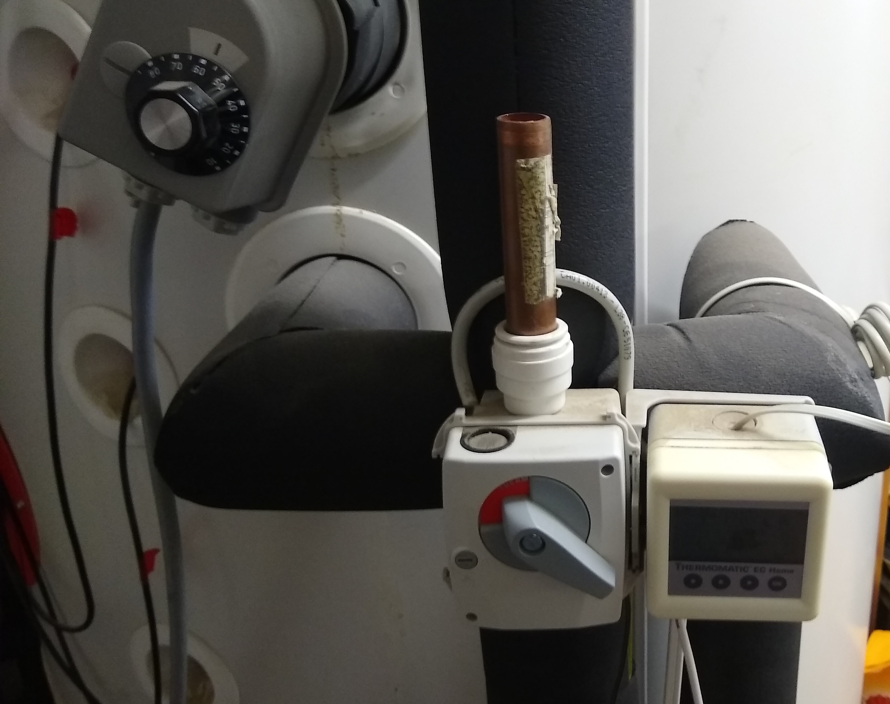
Condenstate? I am not sure that there us any condensate in a ASHP system.
That copper pipe is the emergency overflow incase the hot water tank boils and needs to vent. Its end is covered with a cage outside to stop anyone scalding themselves.
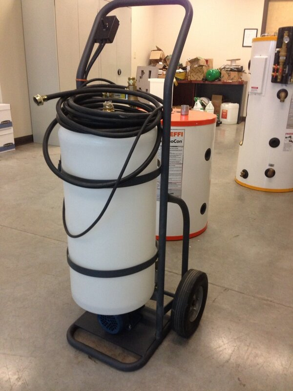
The other issue with breaking into the pipework to install your own flow meter, is introducing air into the system. Once air is in the pipework, it tends to get caught in awkward places, like inside the coil of the DHW cylinder, high radiator points, sometines cavitating in pumps and overhead pipes in roof spaces (especially if no air vents are installed in that section). Air will in turn restrict flow, the very thing you’re wanting to monitor and improve. Removing this air is not just a case of “bleeding the rads”. Quite often a flush & purge cart needs to be connected to force the air out the system.
I would also second the opinion that more lagging is needed on those pipes in the roof space and the joints. After all, you don’t want to heat the roof space
Lastly - ASHPs do produce condensate, as part of the defrost process. The evaporator will need to defrost every so often in the cooler weather and that defrosted condensate usually trickles out of the bottom of the machine outside and into a soak away (and not on the patio slabs where it forms sheet ice and a slipping hazard!) Seen some shonky installs before
If there are inline strainers then generally there are isolation valves near to it, When the strainer is put back in the trick is to open one of the valves a little to flood the filter chamber area and push the air out before doing up the door to the filter strainer. Slight loss of pressure is then topped up with the filling loop.
Changing a circulation pump will invaribly introduce air into the pipework. In many cases it should be actively purged out. Whilst air will rise to the highest points of an installation where air vents should be installed, there are often places where air will be trapped and needs to be forced out by a big circulation pump.
One of these sort of things is a professional cart. One of the plumbers in our company makes his own cart. Take one small wheelie bin, one huge Clarke sump pump and a few hydraulic fittings and a flush cart is made. Connect it to the main flow & return points that are tee’d into the installation and it will be able to flush out debris and air.