I’m about to install an ASHP and looking forward to implementing OEM’s latest heat pump monitor. I had a couple of questions in relation to my intended setup pictured below.
As the ASHP, dedicated CU and Heat Meter are located some distance from my emonpi, I assumed it would be better to implement the separate OEM Heat Pump monitor. This would also ensure interfacing with the MBus equipment. Ultimately I’d like all the readings to be reconciled on the emonPI (alongside the various other jobs it’s doing). Is this simply accomplished via MQTT?
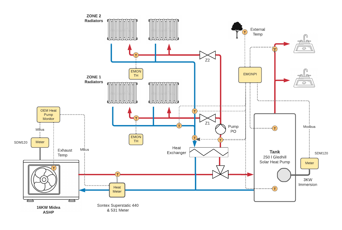
The intended DS18B20 temp probe locations are shown on the diagram in yellow. I’ve attempted to position these in the most optimal strategic locations to provide the most useful temperature data throughout the system (sealed thermowells within pipework). With that, I’d appreciate any further guidance or alternative view on where and how to position these as they have not yet been positioned. While they are easy to place, i’d like to avoid any superflous sensors and, more importantly, not miss an opportunity to place other sensors that may be helpful. The furthest radiators and taps are approximately 50m away from the ASHP.
I respect this may be a daft question - is it possible to have two instances of emoncms running concurrently, with one feeding data to the other as a master? I’d be v. grateful for any insight or experience here before I proceed with this intended setup.
But why? The short answer is yes - that’s what you do if you have an emonPi or emonBase locally and also feed the data to emoncms.org. Two on the same machine - @borpin or @TrystanLea might be able to answer that one, I would think it would lead to untold difficulties unless each was sandboxed to a greater or lesser extent. I’m not an OS expert so that’s only my gut feeling.
Thank you @Robert.Wall, that’s helpful - This is really down to my limited understanding of how the OEM Heat Pump monitor works and how this would operate in conjunction with an existing emonpi.
I suppose the real question is whether my proposed approach of using a OEM heat pump monitor alongside my emonpi is a sensible approach or whether I should be trying to do everything through the emonpi and thus lay the additional 20m of mbus cable needed to support this. This would be a bit of agro if so as the emonpi is some distance from the ASHP and already doing some modbus stuff (vs. the mbus communication required for the ASHP that is not native to emonpi, unlike OEMs dedicated Heat Pump board).
The builders tack my ceiling on Monday so I have 36 hrs to decide!
I think what you are really asking is, can you have the heat pump monitor hat working into one emonCMS on one RPi and everything else on an existing emonPi running another emonCMS, and have the two communicate?
I don’t know in detail the requirement for the heat pump monitor, so I can’t give you a definitive answer. If you already have Ethernet or wireless LAN reaching both places, that’s possibly the best, maybe only, solution. As the heat pump monitor is a RPi hat, I would question whether it can be added to an emonBase or an emonPi without losing the radio capability. In any case, I think my colleague @borpin would recommend one Pi per task.
Whatever you decide, if you’re having work done, lay some plastic pipes joining strategic places so that you can thread cables to your heart’s content later.
Many thanks, that’s helpful - I’ve reread things and seems I just point the MQTT of the Heat Pump hat to my emonpi. I’ll make the jump and give it a go. Thank you sir.
Hello Ben, sorry to not reply on this earlier, yes you can just point the MQTT from the Pi with the heat pump monitor hat to your main emonPi (that’s the configuration I use personally). Running a long MBUS cable is also fine, though I guess you’d then need to run a longer cable for your exhaust/air-off temperature sensor…
Are you planning to use an 2x emontx units for those radiator flow temperatures or can you run the cables back to the emonPi for those, or did you intend to use emonTH units? EmonTx units seem like overkill perhaps for single temperature measurements ? could they be coupled with an emonTH perhaps to give you room temperature monitoring as well?
Thanks @TrystanLea, much appreciated - I realised that was a typo with the emontx on the diagram - meant emonth I have been using them for a few months now - always impressed by their efficiency and versatility. May I also ask if the temp sensors look appropriately placed (and useful) given your experience here? We are trying to use inline thermowells where possible so slightly more committing for our plumber. Also a small window of opportunity to place additional pockets if necessary.
Another question on the Heat Pump hat if I may - would it be straightforward in your view to add a third Mbus device here (a second SDM120-mbus) to monitor the immersion heater independently? If not I’ll stick with the modbus versions going to the emonpi directly but might be a bit daft of me if they’re both side by side in the same dedicated CU…
Hello Ben, looking at the diagram a bit closer (nice diagram btw!) im slightly confused by why there is a heat exchanger between the heat pump and radiator zones? or is it a low loss header?
Temperature sensor locations look good to me.
Yes it’s straightforward to add a 3rd MBUS device. The only slightly fiddly bit at the moment is setting the MBUS addresses of each meter so that they are unique. I’ve been using that little script I posted in the other thread, but I should really turn that into a little command line utility (or ideally something that could be actioned from the emoncms UI), I also need to link it into the documentation properly.
Good question re: the heat exchanger, appreciate the heads up. I have only been able to go by a schematic my installer provided (in advance of unit arriving end of Nov) which shows a plate heat exchanger here. I may have misinterpreted something though and will know next week. Regardless I suppose I’m just trying to determine whether I should install a temp pocket on the flow of a secondary circuit (assuming I’ll have one) - sounds like I should though.
I was largely guided by John Cantor’s superb book and accompanying articles on this topic, which I’m hoping I’ve interpreted OK. As for my installer, they think I’m mad!
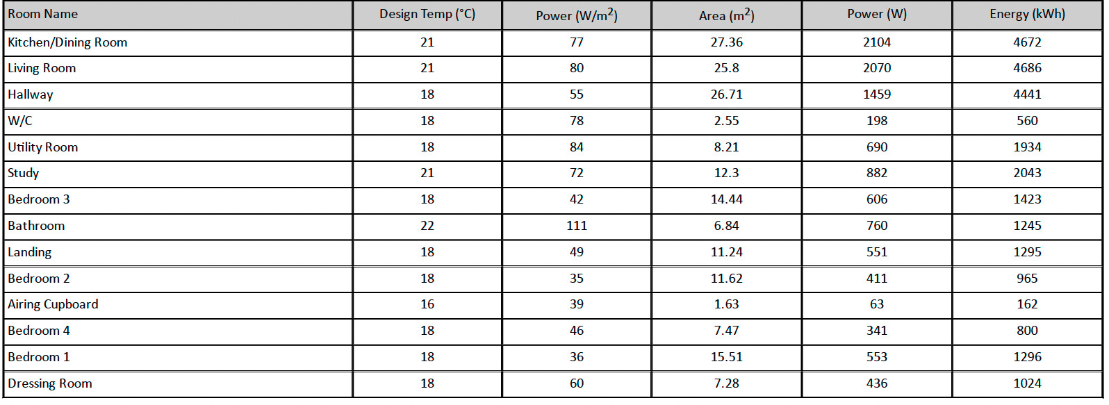
Great, yes seems strange to me to have a heat exchanger there, it would be worth checking as you might be able to do without it and the secondary pump it would then also require… it looks like a simple system that could be driven directly, that said it’s a 16 kw heat pump, what is your heat loss at design temp? is it a large property with extensive radiator system?
Thanks for the feedback and instincts on this, Trystan - really appreciated. I will query with the installer.
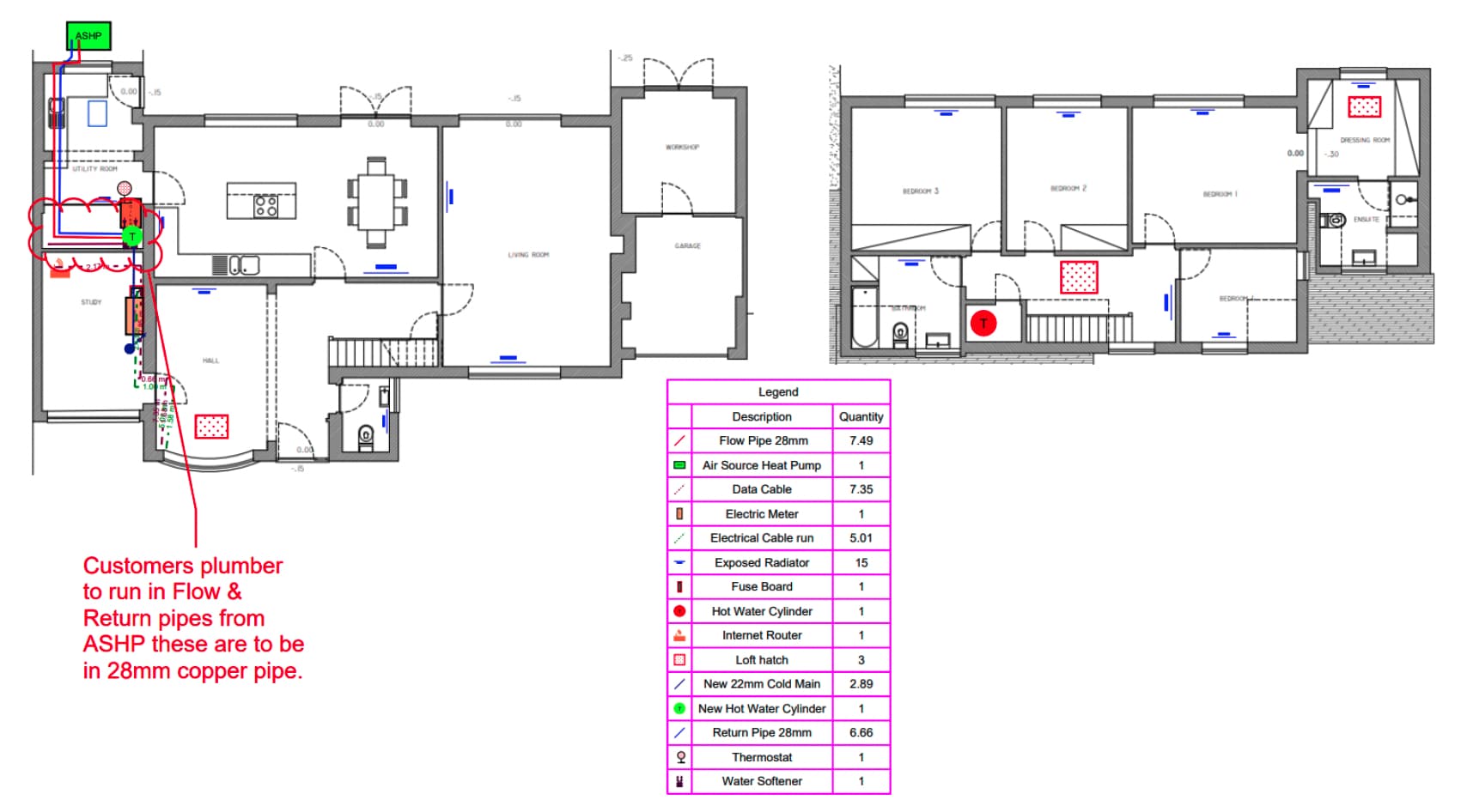
By way of some more context, it’s a fairly conventional 1970’s detached, brick house. About 2,000 sqft of heated space via. conventional radiator system (new plumbing, tank and rads, no underfloor heating). The heat demand is approx. 12kw at design temp. I understand the 16kw is proabbly oversized (we originally had a 14kw ecodan going in) but switched to the Midea last minute on advice from the installer. Floor plan of the install is below. I think I’ll ask them if we can do without secondary circuit.
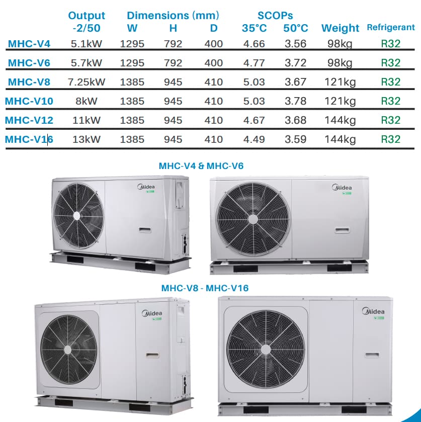
Thanks for the detail, interesting, does 26,546 kWh of annual demand match up with your current heating bills? It’s always quite difficult to get this right as your starting with a theoretical calculation of heat demand that will have large error margins associated with it, you can understand your installers reluctance to keep to a tight margin on the sizing… on the other hand as you know Im sure, there does seem to be a lot of over-sizing going on that negatively affects performance when it’s warmer… Is the midea a double height unit like this one? Midea air to water heat pump 16Kw MGC-V16W/D2RN1 DC Inverter do you have the model number by any chance? I wonder what the minimum modulation level is on the unit it may be able to cope well with running at a low level, it seems some have greater modulation ranges than others…
This is our first winter in the house (which has since been heavily modified) so I don’t have a tremendous baseline for heat demand.
I’m now v. wary of oversizing (and wish I’d read John Cantor’s book before I’d ordered which does emphasise the care needed to balance the HP power rating). That said, I’m let to believe this brand has been more liberal with its performance estimates so hoping I was right to agree to the 16kw vs. the 14.
Interestingly, it’s a single fan unit which was one of the reasons we opted to try this newer market entrant. Time will tell.
While over my head at this stage, I’m intrigued by the Modbus control and telemetry
Nice diagram… looks like you have thought it through well. The only thing I can think of (to elaborate in what Trystan thought) is if one of your zones has a lot of TRVs closed considerably, the return may be quite cool, but also the flow rate might be very low. By also having a common return sensor, you would be able to estimate the ratio of flow rates between Z1 and Z2. As you say, you don’t want too many sensors.
I guess the heat exchanger is mainly there so you only need glycol in the heat pump part of the circuit. It will be interesting to see the temperature difference across the heat exchanger
Thank you, sir. So you would consider one final sensor at the last possible point on the secondary return to low loss header (or heat exchanger), or simply change the position of Zone 1 sensor to include both zones?
On a separate note, given the option would there be any value in monitoring the temperature of the incoming water main at all…or am I going a bit mad now?!
Thanks again. Your book has been a tremendous help.
Its hard to know. its definitely good to know the return to heat exchanger. When either Z1 or Z2 valve is off, the sensor temperatures will ‘float’, with no water flowing, so can be confusing. The good thing about having the 3 return sensors is that you can glean what is flowing… if anything.
I find it good to have more than one cylinder sensor. you might want to move it about. e.g. if 1/2 way up, you get an idea of what is left in the tank, and can also (possibly) maximise COP by allowing the bottom of the cylinder to cool before heating. Maybe you want the lower cylinder sensor at the same position as the ASHP cylinder sensor.
Will be interesting to see the results
Looking forward to hearing the results of your install as well. Especially that temperature drop across the heat exchanger as @johncantor mentioned. Will you be measuring the flow temperature to the radiators coming off the heat exchanger or are those emonTH points at the end of long pipe runs?
Interestingly the Midea installation manual seems to insist on either a heat exchanger or a buffer… The -2C output of 13kW suggests that it’s maybe closer to your heat loss when it’s really cold.
Maybe fit one of the EmonTH’s temporarily on the flow from heat-exchanger. This would give you an assessment of the heat-exchanger dt, also an idea of any pipe loss, not that it matters if its useful to the house…


 I have been using them for a few months now - always impressed by their efficiency and versatility. May I also ask if the temp sensors look appropriately placed (and useful) given your experience here? We are trying to use inline thermowells where possible so slightly more committing for our plumber. Also a small window of opportunity to place additional pockets if necessary.