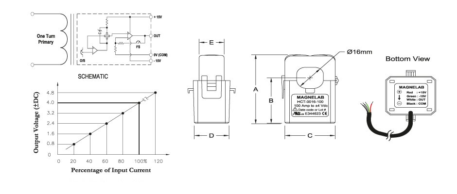
I am using a Magnelab HCT-0016 Hall Effect Split-Core Current Transducer as a DC current sensor. I was just wondering if this sensor will work with emonlib? if not, then how would I write my own sketch to read the output for such type of sensor. Please find the sensor data sheet below.
You don’t need, and must not use, emonLib for a d.c. sensor. It is only for a.c. (What will happen is, the filter that is there to remove the d.c. component of the a.c wave will remove your wanted d.c., so you will get only a small pulse out when the current changes - which is not what you want.)
You simply feed the output into the analogue input of your ADC. The value you read will be proportional to current. If your current is bi-directional, then you must (probably, unless your ADC can accept inputs that go either side of 0 V) offset the 0 V (common) line so that it is at the middle of the ADC input range, and subtract that offset from the number you read. You will then also need to divide down the output voltage so that the maximum swing (in each direction) always remains within the input range of your ADC input.
I implemented the given below code but I have an error about 0.2 in the reading. Would you like give me any suggestion. By the way, I am using ATMEGA328P microcontroller.
#define NUM_SAMPLES 150

int sum = 0;
unsigned char sample_count = 0;
float Current = 0.0;

void setup() {
  // put your setup code here, to run once:

  Serial.begin(9600);

}

void loop() {
  // put your main code here, to run repeatedly:

    while (sample_count < NUM_SAMPLES) {
        sum += analogRead(PC3);
        sample_count++;
        delay(10);
    }

  float Current = ((float)sum / (float)NUM_SAMPLES * 3.3) / 1024.0;

    Serial.print("Current: ");
    Serial.print(Current/0.04);
    Serial.println (" A");
    sample_count = 0;
    sum = 0;
}
You need to go through the sketch doing the maths by hand!
analogRead can have a maximum value of 1023.
If you sum 150 of those, you get 153450. But it’s going into a signed integer (sum). What is the maximum value that a signed integer can hold?
What do you read with no current?
Does it read correctly up to 17.6 A?
Without knowing how you’ve connected the transducer, there might also be a problem with your hardware.
According to the Spec sheet, 100A should produce 4V, +/- 1%. Going through the maths in your code
float Current = ((float)sum / (float)NUM_SAMPLES * 3.3) / 1024.0;
Is how you convert your Raw ADC values into an average Voltage. That line is assuming that an ADC value of 1024 (which should be 1023 as indicated by @Robert.Wall) is equal to 3.3V. Have you checked that? Are you using the built-in regulator on the Arduino or a fixed, well known 3.3V input?
Here’s a function I wrote for measuring battery voltage for some of my battery powered projects. I’m using mV as the units, avoiding floats entirely and using unsigned variables. This has been working perfectly for well over 2 years now:
#define VCC_VALUE 3288 // This is the voltage value on the VCC pin - measured in mV
#define VDIV_RATIO 1.3169 // 2185+6900/6900 This is the ratio between the batt ref voltage divider R's

uint16_t getBattmV() {
	const uint8_t reps = 5;
	uint32_t avg;
	uint16_t sum = 0;

	for (uint8_t i = 0; i < reps; i++) {
		sum += analogRead(battPin);
	}
	avg = sum / reps;
	avg = avg * VCC_VALUE / 1023;
	return ((uint16_t)(avg * VDIV_RATIO));
}
You only need the VDIV_RATIO if you have a voltage divider to reduce your voltage, but you can see that its basically the same calculations you are doing, with just slightly different values.
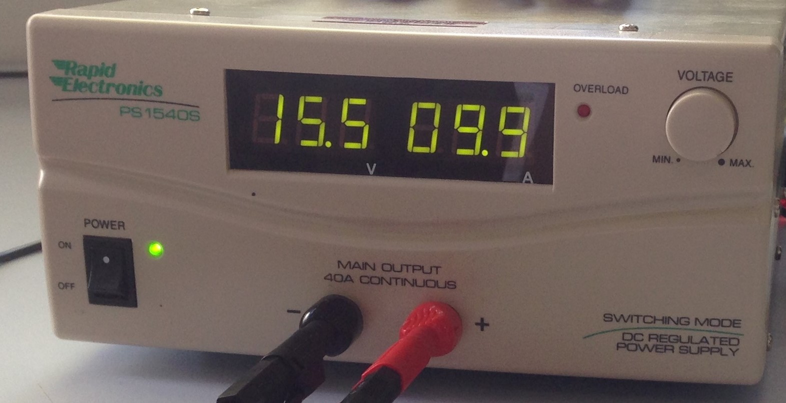
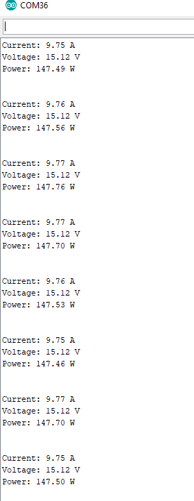
It may also be worth putting a voltmeter on the output of your transducer when you are at 9.9A to see if you do in fact read (9.9/100*4=) 0.396 V. If you’re reading 0.390V, that will give 9.75A.
Just to put all of that into “ADC units” assuming 3.3V input:
0.390V = 121 (121 = 390.322mV which converts to 9.758A)
0.396V = 123 (123 = 396.774mV which converts to 9.919A)
for completeness, 122 = 393.548mV which converts to 9.839A
So that is an idea of the accuracy you can expect.
I think you need to mention how you get the voltage onto the battPin.
It’s worth noting that there are two approaches to obtaining an accurate measurement. The emonTx V2 relied on the internal band gap reference of the Atmel 328P to determine the supply voltage - and hence the analog reference. The internal band gap reference’s initial value is subject to a large uncertainty, however it is relatively quite stable against supply voltage provided that the chip temperature remains constant.
The approach used in the emonTx V3.4 is to rely on a regulator with a more precisely known 3.3 V output, to use as both the supply and the analog reference, and to disregard the internal reference.
The code above is for a node using a LiPo and battPin is defined as one of the analog ports which is connected to a voltage divider between the battery terminals like so:
+ ------\
     2185R
B       |
A       +---------- ADC Pin
T       |
      4715R
- -----/
This drops the 4.2V full voltage down to an acceptable level for the 3.3V Arduino.
I’m using analogReference(DEFAULT) (well, not actually using anything, so relying on the default) and I define VCC as the voltage measured on the VCC pin - as described in the comment in the code above.
[EDIT] The R values were chosen because I had them to hand (2.2K and 4.7K). The actual R values were measured using a Fluke multi-meter.
The sensitivity sense of the sensor is 0.04V/A. For final current value, I simply divided ADC value by 0.04 .
Serial.print(Current/0.04) function.
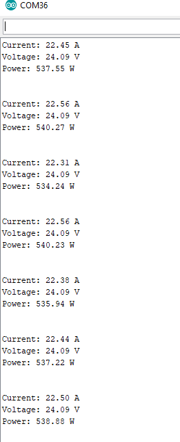
I used two while statement in code, one for current measurement and another for voltage measurement for the real power measurement. But, with no current or voltage sensor, I am still getting a reading. How could I fix this?
updated code.
#define CURRENT_NUM_SAMPLES 100
#define VOLTAGE_NUM_SAMPLES 100

#define VD_RATIO 22.96211251
#define CV_RATIO 0.04
#define GLOBEL_CAL 0.144

double CurrentSum = 0;
unsigned char Current_sample_count = 0;
float Current = 0.0;

double VoltageSum = 0;
unsigned char Voltage_sample_count = 0;
float voltage = 0.0;

void setup() {
  // put your setup code here, to run once:

  Serial.begin(9600);
}

void loop() {
  // put your main code here, to run repeatedly:

    while (Current_sample_count < CURRENT_NUM_SAMPLES) {
        CurrentSum += analogRead(PC3);
        Current_sample_count++;
        //delay(10);
    }

    while (Voltage_sample_count < VOLTAGE_NUM_SAMPLES) {
        VoltageSum += analogRead(PC0);
        Voltage_sample_count++;
        //delay(10);
    }

    float Current = (((float)CurrentSum / (float)CURRENT_NUM_SAMPLES * 3.3028) / 1023.0)/CV_RATIO;
    Serial.print("Current: ");
    Serial.print(Current);
    Serial.println (" A");
    Current_sample_count = 0;
    CurrentSum = 0;

    float voltage = (((float)VoltageSum / (float)VOLTAGE_NUM_SAMPLES * 3.3028) / 1023.0)*VD_RATIO;
    Serial.print("Voltage: ");
    Serial.print(voltage+GLOBEL_CAL);
    Serial.println (" V");
    Voltage_sample_count = 0;
    VoltageSum = 0;

    Serial.print("Power: ");
    Serial.print(voltage*Current);
    Serial.println (" W\n\n");
    delay(1000);

}
No, when I connect the current sensor to the boardd then I am getting right reading. But when i unplugged it then i am still getting. So, i think this is because of two while function in one loop.
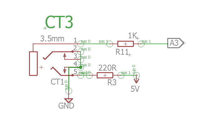
The sensor interfacing with arduino is
Ignore the 5V input voltage as this sensor using +/-15 which I am powering from the external power supply.
Please understand that the only things I (and anyone else here) knows about what you are doing is what you have written in this thread. We do not know anything else.
So trying to put together the tiny pieces of information that you are providing one by one, am I right with:
You get the correct voltage reading always.
When you connect the current sensor, you get the correct current reading.
When you disconnect the current sensor and have no connection to A3, then you read something, when you expect to read zero.
If nos.1 & 2 are correct, then if no.3 is correct, it is because the ADC input voltage is not defined. It is a high impedance input and it can and will take up any voltage between zero and VCC. If you must read a true zero when no plug is inserted into the socket, you must connect a high value resistor between A3 (or better, pin 1 of the socket) & GND. “High” means large enough to not alter the reading when the transducer is connected and working. I would guess that a resistor > 50 kΩ should be large enough, while still being small enough to ensure an accurate zero reading.
Where is the transducer and its power supply on that ‘interfacing’ drawing? How does the transducer COM connect to the Arduino GND?
The problem is your hardware, nothing connected with the averaging software loop.
I have another question regarding EmonCMS. I brought the emonSD and now I am trying to connect my board to the emonCMS but it is not working. What do I need to change in the emonSD to work with my board and do I need to update SD card, such as, read and write API key. I am new user and don’t know about the emoncms. If you give step by step instructions. it would be very helpful.
You are being very secretive. What board? Which emonCMS? How are you trying to connect? What are you trying to send? Does your data conform to the format that emonHub expects?
All the instructions for emonCMS are in the “Guide” section. This assumes you are using our standard set-up - an emonPi or emonBase, optionally receiving data from one or more emonTx or emonTH.
If you have anything different, then you must arrange to send your data in a compatible format. You should probably not change anything other than the configuration files in the standard emonHub/emonCMS combination to suit your sketch, but rather make your sketch compatible with our standard. That way, you will be able to update emonCMS without having to rewrite it every time.
what board?
A single phase emonpi based on atmega328P micro controller., which is consist of three CT input (CT1 = pin 26, CT2 = pin 19 and CT3 = pin 22) and a AC-AC reference voltage ( pin 23).
2.Which emonCMS?
Local
3.How are you trying to connect?
With RasberryPI 3 MODEL B
4.What are you trying to send?
Current, Voltage and Power
Does your data conform to the format that emonHub expects?
Don’t know
Hello @Robert.Wall, I am working on the same PCB with @irfiee.
Here, we have not used the RFM12 module on our PCB (emonpi board), is there any other way to send the data to the local host emoncms?