GTI Limiter / Diverter for wind and solar

hi there ,
just wanted to share my projects with others, it seams to work well for me perhaps others would find it useful.
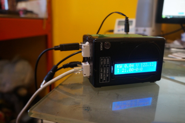
most projects are solar diverters. which is fine this one built is GTI limiter, it reduces the input load to the GTI via PWM. but also can diverts that excess dc load to another DC device or storage battery using pwm it controls 6 pwm at a time , it also can monitor wind generator GTI and use dump load to reduce its out put to grid. you can enable and disable application within the firmware .
option are:
1 it to determines the dump load - and makes calculations on that for triac ( just basically an ease of use function)
2 ) calculated inverter output and adjust pwm to limit GTI output
3) measure wind generator output, and adjust triac for dump load

parts reqired:
uno
emontx shield
triac (bta41) Home | OpenEnergyMonitor
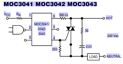
MOC3061 or MOC3043M
AD5206 (100k) https://www.arduino.cc/en/Tutorial/DigitalPotControl
led
ic chip socket for ad5206
header pins
misc resistor and caps (see linked webites for specifics)
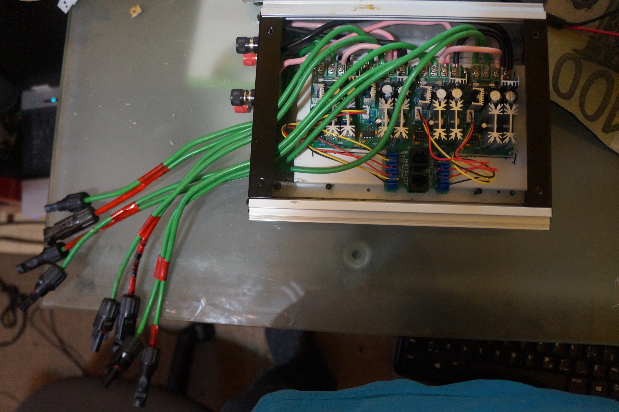
dc motor speed regulator - 20 - 100 amp PWM HHO http://www.ebay.ca/sch/i.html?_from=R40&_trksid=p2047675.m570.l1313.TR0.TRC0.H0.TRS0&_nkw=PWM+HHO&_sacat=0
cat5 module jacks (RJ11/RJ45/RG12)
bnc connectors
cat5

I used uno for my project, so i had to make some modification to the emontx shield.
modifications to emontx shield as followed - pull a4 pin ( other choice id cut trace or remove burder resistor on ct4) - you only have to do this if you want LCD screen to display information such grid, solar inverter or wind inverter outputs) so that the LCD-L2c screen will work otherwise it will freezes uno at lcd screen boot

when you assemble the emontx shield do not solider in the iscp block - instead install header in middle section on top to give access to pin 13 ( clk) 11(sd1) for ad5206 chip we just use the preexisting header pins on the emontx for the other dig ports

lcd-l2c pins out on scl sda on uno gnd and 5v

construct ad5206 module as described here https://www.arduino.cc/en/Tutorial/DigitalPotControl
pin out on pin 13, 11 and 10 as described (pin 10 is found is found on preexisting emomtx header pins) and solider cat5 wire to chip socket for ad5206 chip and jumper wires for uno board and then connect to cat5 module jack of the cat 5 wire
on the other end build another module to be able to attach cat 5 wire to pmws or simply clip the pot off the pwm hho and push the corresponding wire into the correct location on the rg45 module jack each cat 5 or telephone wire will handle 2 pmw each attach to correctly to the dc side of your solar panel and GTI - standard cat cable to desired length to connect uno device to pwm modules

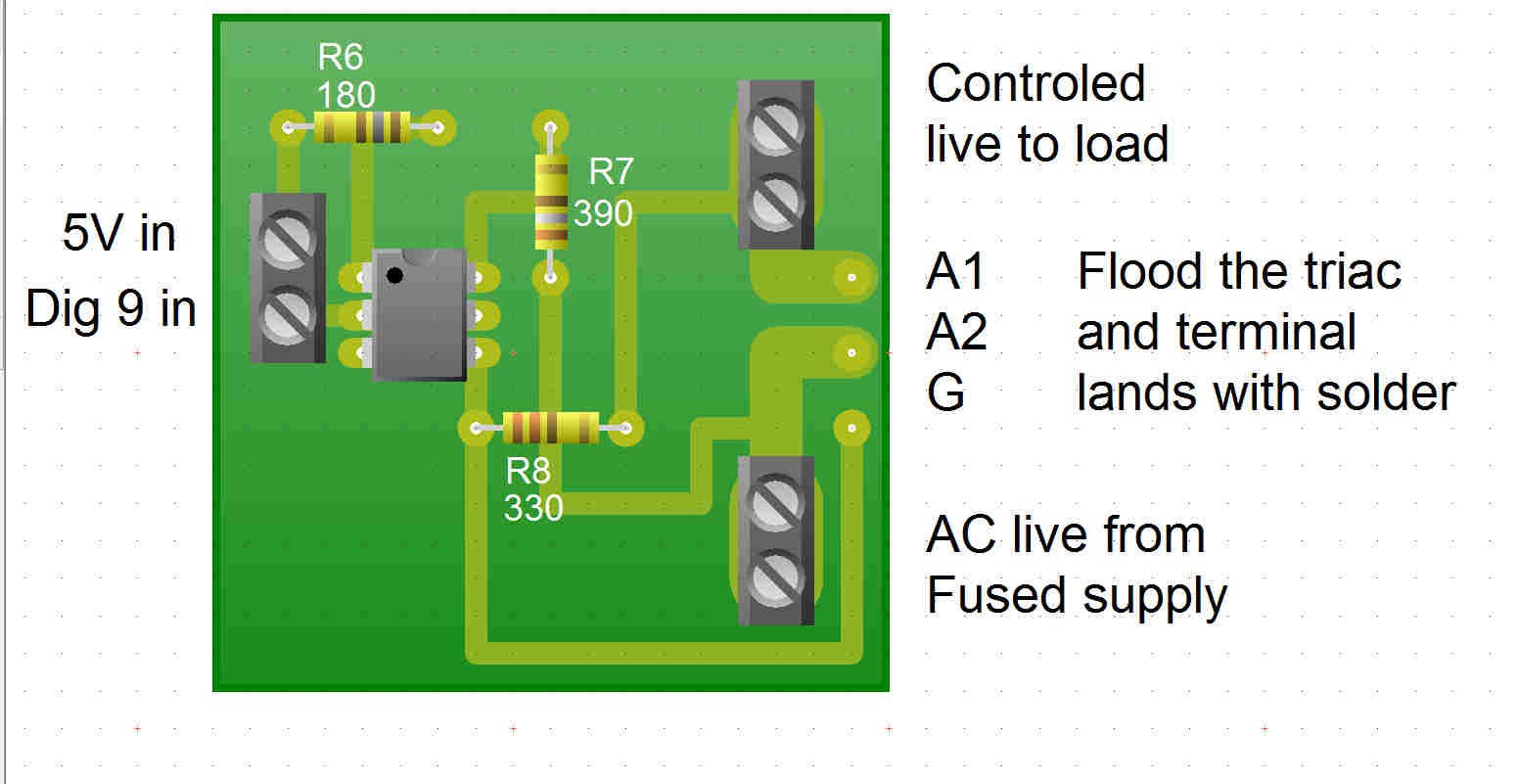
construct remote triac module as described in these links
https://openenergymonitor.org/emon/Choosing%20an%20Energy%20Diverter
http://www.kerrywong.com/2010/09/11/a-high-current-triac-controller-using-arduino/
using a female bcn for input.
on ardinno for triac output it pins out on gnd and dig 5 ( same header pin as dig 10 is located) to a female bcn - male bnc cable to length
when installing on water tank I would install a second or preexsisting phsyical bimetallic hotwater tank switch. and set it at the max temp so if the tank over heats it shut it off. also i would consider wiring it though the preexisting wiring on the tank so the the emergency pop works also so that you do not accidentally cause an hotwater tank explosion, if for some reason of triac failure and bimetalic switch failure and it stuck on position

GTI_Limiter-Diverter.ino (12.3 KB)

pin 3 i used for a led it brightness determines how much power is being dumped diverted or limited

the sketch is stil has some redundant info and debugging needs a little clean up but works fine otherwise
good luck have fun :slight_smile:

here a picture of my finished unit – it working very nice - though I have not built the diverter yet ( waiting for a better opticoupler to come) as there no rush for that . - as i use solar thermals to make my hot water and I have more hotwater then i know what to do with… but hey can not complain I live in the centre of Canada my winters are -40c and I am quite proud of my hybrid heating system a combination of heat pump and evacuated solar tubes – with a heating bill +90% lower then everyone else it pretty darn good I think at +/- 1700 kw a year to heat an average size home per year - now i am trying my hand at PV panels so see if I can reduce grid consumption even more

here the picture of the finished GTI limiter module - I am only using 4 of the possible 6 digital pots - I used a case form a dead GTI I had . depending how it wired it can handle up to +4kw of solar panels I have this one configured to handle 2 kw each post set is one kw . but you can build the limiter as big as you need , for this particular one I used 60v 20amp pwm as I liked them the most as it has built in fuses and for $5 each dirt cheap

Hi Stephen,

You say you use 1700kW (I presume you mean kWh?) to heat your average size home for the year.
Is this 1700kWh in total or 1700kWh that you buy from the grid?
Also what the actual foot print of your “average” home, so we can compare like with like?

I must be missing something, as I thought my home was fairly average sized at approx 120 sq m, with above average insulation, double/triple glazing, and a modern/efficient gas to radiator central heating. But I still burn 4000kWh of gas a year, and I run the heating as little as possible. Instead preferring to use my wood burning stove, I estimate (very roughly) that I use between 1500kWh and 2500kWh of wood over a bad UK heating season. Even at 6500kWh, I’m still classed as well below a ‘low user’ of gas in the UK, but our winters don’t get down to anywhere near -40’C. So what am I missing here?

yes 1700 kwh and my home is ~ 120 sqm to . r 20 walls, r50 ceiling, r12 floor. i do not really have triple glazed ( only the 3 windows on the northeast side) . As most of my windows are south west facing . you get more heat gain from double glaze then heat loss. i have alpine roof to naturally shade the widows in the summertime.

prior to my upgrades i used conventional heating methods (electric heat) - and I consumed average ~15000 kwh per year to heat my house… the heating season for me is generally 7 months.

what i did is I install 7 kw heat pump ( consumes about 1.7 kw) and 7kw of evacuated solar tubes that produces both my heat and my hot-water… the heat pump reduces energy requirement by +66% and the solar tubes reduce it again +66% the average heat energy required - 15000 - 66% = 5100 - 66% = ~1700.kwh -
generally people here heating season starts about mid October to mid May- my evacuated solar tubes shorten that to Dec - Feb. and generally for Oct, Nov, Mar, April, May it does nearly ~ 80 - 100% of my house heating . and for those colder darker months depending on the the winter 30 - 60% of the heating. the thing is the milder the winter is the cloudier it is the colder it is then more sunnier it is , so it offsets and compensates.
since i have a large bank of solar collectors I shade 1/2 in the summer . but not really required as when my thermal buffer tanks reach their max temp (I just do it to reduce wear and tear ) the excess heat is dumped into the ground loop of the heat pump . which in turn increases the efficiency of my heat pump as the soil is much warmer then usual…

I hope I explained what you’re missing – here an article about me from a couple weeks ago it on the second page Express Weekly News

here a couple images of my house and the evacuated solar tubes there are 7 collectors 3 are a bit hidden but they are roughly where the solar panel is

I burn no wood for this result. and with milder winter where it much less then 1700 - out of curiosity - last winter I installed a emergency back up heating system in my green house ( as seen in the picture.) it a wood boiler that would heat my home in case of extended power outage . I tested it last winter for the heck of it. . but I tested for too long of a period and my green house came alive so I had to continue to heat for the remaining of the winter (about 2 cords of wood) it kept my green house ( 70 sqm) at +10c and my house warm that my heating bill was <500 kwh

here a basic image of my system lay out. I posted it on another website probably close to 10 years ago but that website does not exist any more ( interesting discussions)

my personal system is a bit more complex as i try to squeeze every bit of heat energy i can ( ie; in the dead winter when the sun is at it lowest and it is overcast, generally the evacuated solar collectors only produce max temp of ~40C which is cooler then min of my 200 gallon buffertank ( 48c)under these conditions, my system shifts this automatically to the solar heat to the ground loop which boosts the efficiency of the heat pump so instead of COP of 3-4 (at ground temp of 10 - 15c) it jumps to COP 4-5 creeping sometimes to COP of 6 (15- 25c)

also here a free software that i recommend to people who want to get their infrastructure to the best energy efficiency at the lowest cost . you can adjust your upgrade to where you thing they do the most good. http://www.remrate.com/ either design or desktop each work about the same

Ah, a Ground Source Heat Pump, that makes sense!

I guess even in the cold winters you have plenty of sunshine to drive the Heat Pump?
Hear in the UK, with 4kW PV on the roof, I struggle to get 3kWh day on an average December day :frowning:

You say your Heat Pump is a 7kW model? It take in 1.7kW and pumps out 7kW?
Also, how long and how deep is your ground loop?

I would guess that the two cords of (hard)wood you used that winter added about 13,000 kWh of heat to the greenhouse and house, it proves how good your heating system is!

By the way, I must say I love the electric utility vehicle - especially the 250W panel on the roof! :slight_smile:

well no real PV yet- they are solar evacuated they produce pure heat . i am adding this year PV close to 4kw. i installed a solar water pump last month ( that works great). generally the average should only be about 50% for dead of winter ( dec - feb)… but if it cold it usually very sunny then the output is closer to 60 - 80%. ( but dec is usually quite overcast- jan and feb are general sunny) basically depending how cold if warmer then -10c one day of good sunshine I can store enough heat in my buffer tanks to last to the next day possibly 2 days ( maintaining indoor temp around 20c - 22 c) if cooler then this then my heat pump may or may not kick in but usually it would be around 6hrs after the sun gone down then run for 1-2 hours after the sun comes up again… but usually if colder then - 20c there not a cloud in the sky - if around -10c it quite overcast. so it averages out on average to about +50% output for dead of winter -

my ground loop is 800 feet long at 6-7 foot depth.

my wood was basically scrap wood i just cleaned up dead fall around the the yard. some was soft, some hard other . half rotten. (was not expecting to heat with it last year. it just once I started I could not stop - my fruit trees in the greenhouse ( plus everything else bloomed at the end of January ( which sucked made lots of extra work for me)

me too i love it too the electric utility vehicle – it so handy. especially with the 2kw inverter on it . and that it self charges if i drive less then 10 miles a day with it I may not plug it in to charge it all summer .

just an update - my opticouples came- moc3041 and moc3043 when I built my diverted board I used IC sockets for easy swapping of chips . and the moc3043 is far superior to using the moc3041 that often used on this site. It seam to get a full 254 steps with it so if I am using a 2000 watt diverting shunt of some form it getting ~8 watts per step accuracy … and with the moc3041 I was only getting a range of 10 steps or 200 watt accuracy

The only difference between the MOC3041 and MOC3043 is the LED Trigger current. So if you experienced a difference in performance, you were not driving it properly.

I would offer a word of caution about the use of sockets - you need to ensure that the correct creepage distances are maintained between the high voltage and low voltage sides.

while if that the case of only voltage. then . since it in a socket and it working fine with one chip and complete different with another ( that under 120 volt conditions) I can not see how it being driven is the problem . perhaps my moc3041 are not working properly ( as I bought 10 for a $1) or the out come I get is due to 120 volt load as compared to 240 volt load. which in that case Does that not make the moc3043 a better chip to use in N.A due to the differing voltages we have ? - I will try 240 today and see if there is any difference

If you look at the data sheet, you will see that for a 115-120 V supply, the resistor values are different. You cannot expect correct operation with the wrong values in the circuit. From the description of operation that you give, I can easily see how having the wrong resistors could give rise to those symptoms, I could not see how the LED current could. I suggest you change the resistors to the values shown in the data sheet.

humm this is the configuration that i used… the moc3043 is working fine with both the 120 and 240… even rebuilt it on a peg board the new peg board one worked the same

but from my experiment from today it looks like I have to match my solar output to my shunt . my maximum output currently is 1.5 kw but my shunt 4.5 kw ( it is the back up heating element for my heat pump incase of heat pump failure). but I had to set my element size in my sketch to 4 times bigger then ( originally i had it set at 4500 but was over shunting by fair amount on the first step ) then set it to 10000. it offset the step slightly smaller. and the second or third step step would adjust to the proper wattage , i am guessing compensated for the initial surge and variance in the triacs output at various steps . but it was not very stable input from the solar panels as it was very patchy sky today hopefully it is clear sky tomorrow -

also a smaller element should make it more accurate. or i think i might have to use two pwm to output 10 bit instead of 8 bit – i have my test driver board I will give that a try and see if I can get a output more then 255 steps a 1024 steps would be nicer then i could use the 4.5 kw element and have the same accuracy as if i used an smaller element that is same size as my solar panel array

If you check the component values, the 360 Ω and the 330 Ω resistors are different for 120 V operation, although the circuit configuration remains the same.

All that reads as if you’re using an open-loop control system and you’re trying to match the characteristics of many devices. Maybe you should look to closing the loop and derive a feedback signal that will automatically (provided you can stabilise the system) trim the errors that I think are the cause of your problems.

Both MartinR’s and Robin Emley’s diverters are closed-loop systems, because they adjust the dumped power so that the nett power flow to the supply is zero. The alternative, open-loop, method would be to independently measure generation and consumption and then command the load controller hoping that you had done the sums correctly and the measurements were accurate.

hi Robert it seams zeroing out the okish it accuracy is about +/-100 watt. comparing the shunt size 4.5 kw compared to 1.5 maximum upload from the solar which is rough 4 times bigger so it reduces my step to only 50 usable steps . and from what i can tell the kick on wattage 40 - 50 watts and roughly 50 walls per step on the 4500 watt element on real world trial. so either I have to increase my resolution of the pwm from 8 bit to 10 bit . but the simplest would to be reduce the element size if i reduced to 1500 watt element then then it only be a 10 watt per step – as it is it miscalculating by 1-3 steps- so if it only 10 watt per step and that would make it accuracy 20 - 30 watts - i try dropping the element size to match my solar panels and see it works better

hi - i simply moved the on of my 240 legs to the neutral which change the element from 4500 to 1200 watt element at 120 (as before it was working at 240v)
the results are much better ; as it average around 20 watts variable
example:
the first set not used, the second set is the grid info , the third is the invert output curgrid2 is the digital pot step ( not used), curgrida is the step for the diverter
0 -39 1754 122.97 curgrid2 254
curgrida 160

0 34 1771 122.95 curgrid2 0
curgrida 158

0 -4 1770 122.89 curgrid2 254
curgrida 158

0 -14 1772 122.81 curgrid2 254
curgrida 159

0 50 1787 123.39 curgrid2 0
curgrida 156

0 -13 1780 122.95 curgrid2 254
curgrida 157

0 -2 1799 123.41 curgrid2 254
curgrida 157

0 -14 1779 122.89 curgrid2 254
curgrida 158

0 -26 1782 122.89 curgrid2 254
curgrida 159

0 42 1797 123.31 curgrid2 0
curgrida 157

0 5 1765 122.88 curgrid2 0
curgrida 156

0 7 1786 123.39 curgrid2 0
curgrida 156

0 -4 1779 122.83 curgrid2 254
curgrida 156

0 53 1775 122.88 curgrid2 0
curgrida 153

0 -10 1789 123.37 curgrid2 254
curgrida 154

it seams to work well once it passes a about 50 steps- but i do not get why at lower steps it output is such highly variable
example

0 -215 914 123.26 curgrid2 254
curgrida 14

0 203 922 122.99 curgrid2 0
curgrida 1

0 83 932 123.10 curgrid2 0
curgrida 0

0 -238 942 123.30 curgrid2 254
curgrida 16

0 229 954 123.07 curgrid2 0
curgrida 1

for 16 steps it showing 400 watt difference - I guess that could be to resistor difference at 120- have to see if 240 1500 watt element I guess I could change resistors on it and see if it operates more linearly at 120 or find a 2000 watt 240volt element

I don’t understand how you are controlling the triac, and how that relates to PWM. What you have there is a zero-crossing switch, when you enable it, it conducts from the next zero crossing until the zero crossing following your removing the enable signal. You must take care to enable it for a whole number of cycles, otherwise you rectify the a.c. current wave and neither your inverter nor your electricity supplier will be happy.
When you do enable it for whole cycles, the minimum is obviously one, but the ‘off’ time before you enable it again is completely under your control. Therefore you can easily control the average current in your load in steps of, say, 0.4% (~1 cycle in 256). If that is what you are doing, then your PWM has a pulse rate of about 0.2 Hz. But with that sort of rate and duty cycle, you are very likely to have a measurement problem. You will need an averaging time several times that to give you current readings that are accurate, because there may well be a ripple at 0.2 Hz; and I don’t know of a meter that will do that. My point here is, I would be very suspicious of any measurements made on that system unless I knew exactly how the measurements had been made. I think you need to check that the variability you are seeing is not a measurement problem.

oh my triac is just controlled by a simply pwm pin on the uno ( it not controlled by the ad5206 digital pot that something different to control the dc current going into the GTI to reduce GTI output - i am not using that function at all. in this trial just a PWM pin on uno as everyone else is, I am simply using the triac to control the amount of current going to a heating element.

so these weird number I am getting are measurement errors most likely as they are not reading the the current load on the pulse properly – I wonder if the digital meter that the power company is using has the same issue of reading it… okay thank Robert for your response greatly appreciated

You can’t do that - at least, not successfully. You need to understand how triacs (and for that matter, thyristors) work. They inherently latch until the current falls to zero. Therefore, once you’ve turned your triac on, you have no more control over it until it naturally turns off again.

I was trying to work out what would be happening, but I’m struggling to see how you could have any control over the current at all. I’m pretty sure it’s not working how the designers of the MOC3041 intended it to work.

not sure why you say it can not work that way everyone driving the moc304x with the pwm off the ardino.


using the negative volt side of the PWM pulse ( as both are present )
as an example the mk2pv router Robin Emley’s

The way to drive a triac is not PWM in the sense that Arduino use it, i.e. with a frequency in the hundreds of Hz to low kHz range, and certainly not using the Arduino library functions for pseudo-analogue output. The output signal frequency for controlling a triac is, at a maximum, half mains frequency (and indeed needs to be locked to mains frequency for accurate control). There is no minimum frequency - you could turn the triac on for 1 mains cycle per year if you wished (though that’s silly, of course - realistic minimum would be one cycle every few tens of seconds).