Hello,
I’m using the basic config to read at serial monitor the current from my loads(resistive).
The setup is an arduino UNO(Emonlib running) + SCT013-50A with classic voltage divider+capacitor 10uF.
I can see currents with good acuracy only above 1A, so its my question…
How can I read currents like 30…100mA? There is a circuit to solve it?
Thanks in advance
Cheers
The simple answer is no.
Your SCT-013-050 is only specified for accuracy from 10% to 120% of full scale, i.e. 5 A - 60 A.
All c.t’s are inherently inaccurate at low currents, there is nothing you can do about that, it comes from the way the magnetic fields from the windings interact with the core material. The meaning of “low” as a proportion of the rated current generally depends on how much the c.t. costs. All you can do is spend a lot more money on a c.t. that should work more accurately at lower currents.
If you do not want to read the full 50 A, you can of course use multi-turn primary winding for your c.t. 2 turns will give a maximum current of 25 A (you change the calibration to suit), 5 turns will give 10 A, etc, and the minimum sensible reading you get will go down in proportion.
Thanks for the info Robert,
I need to read currents up to 30A in my project but as I had this sensor in my inventory I used it.
I was afraid to read your answer, I really need to read at least 100mA, I was thinking to put 2 CT’s, that mentioned above and other to 5A and connect it in 2 arduino analog pins but probably when the current pass by 5A or above it will damage the CT 5A right?
I am waiting to arrive my new acquisition ACS712-30A, do you think it can be helpful for my project?
Thanks a lot
It probably will not damage the c.t, but it could easily damage the input of your Arduino. The output from the c.t. will “flatten out” as the core saturates, but then the flux changes rapidly on each half-cycle so high voltage spikes are produced. I cannot say with certainty that those voltage spikes will remain inside the Arduino’s input voltage range. If they do not, the Arduino will be permanently damaged.
But have you looked at the data sheet? The sensitivity is 66 mV/A so you have the output voltage swinging ±2.8 V and centred on 2.5 V. It can only go from 0 to +5 V ![]()
Yes, that 30 A is maximum d.c., not rms a.c. That means your maximum current is actually 26.7 A rms, and might be lower - even if you have a 5 V Arduino.
Hello Robert,
I didn’t read that datasheet, my fault  I know that that sensor will not help me but I had another idea:
Is it possible to use 3 analog pins tu read 1 voltage and 2 currents(30A and 5A)?
I decided to keep the Imax of my project to 25A, so I want to split the AC cable in 5 equals parts to divide the Imax/5 and avoid an eventually problem in my CT 5A+arduino port. The schematic is shown below:
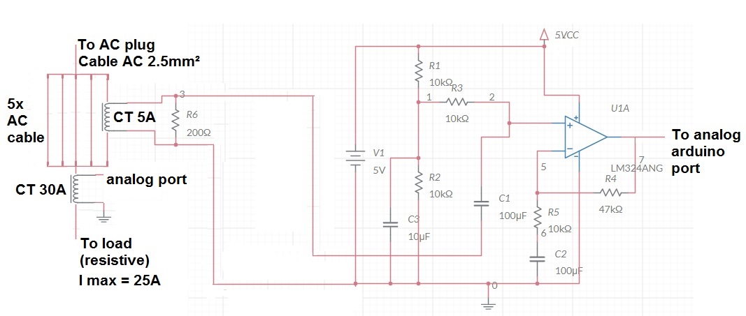
That circuit “sends” the output amplified signal on 2,5V offset to help arduino adc
And assuming that would be possible to use that setup, I’m thinking to use this code:
include…
EnergyMonitor emon1;

EnergyMonitor emon2;
float realPower, apparentPower, powerFActor, supplyVoltage, Irms;
setup()
emon1.voltage(A3, 130.5, 1.7);  // all values are examples, not working yet

emon1.current(A4, 110.0);
emon2.voltage(A3, 130.5, 1.7);

emon2.current(A2, 4.0);
loop()
double Irms = emon2.calcIrms(300);  // Calculate Irms only from CT 5A
if(Irms < 2.5) // checking if will better to use CT 5A or CT 30A

{

emon2.calcVI(50,2000);

realPower      = emon2.realPower;

apparentPower  = emon2.apparentPower;

powerFActor    = emon2.powerFactor;

supplyVoltage  = emon2.Vrms;

Irms           = emon2.Irms;

}

else

{

emon1.calcVI(50,2000);

realPower      = emon1.realPower;

apparentPower  = emon1.apparentPower;

powerFActor    = emon1.powerFactor;

supplyVoltage  = emon1.Vrms;

Irms           = emon1.Irms;

}
emon1.serialprint();   or emon2…

delay(xxxx);
ps: the CT 30A connection is the same shown at learn " measuring mains voltage and current"
Its my first time using emonlib+arduino so I’m so sorry if I am doing a lot of mistakes about connections+code.
Thanks a lot!
I see what you are trying to do, it is similar to what Atmel has already done. Find and download a copy of Atmel’s data sheet AVR465: Single-Phase Power/Energy Meter with Tamper Detection.
That uses the same processor and ADC, and had a gain controlled amplifier that increases the low amplitude input when necessary. That way, they use only one ADC input.
So I think your circuit will work.
[Edit]
Remember there is a time delay while it reads samples and calculates the average: emon2.calcIrms( ) runs for a little more than 3 cycles of mains (about 55 ms), then you run emon2 again (or emon1) when either reads for 25 cycles (416.6 ms I think for you).
“300” is a bad choice for calcIrms( ). For best accuracy, if should be as close as you can get to a whole number of mains cycles, and the sample rate with an Arduino Uno will be approximately 5588 current samples per second (but you should check this with your Arduino).
If the current changes between measuring to decide which c.t. to use, and doing the measurement, then you could have a poor result if the change needed it to use the 5 A c.t., or a wrong result if it needed to use the 30 A c.t. and the op.amp saturated.
[/Edit]
As your 30 A c.t. has a built-in burden, the calibration is wrong. It should be 30. You’ll need to adjust the calibration on the 5 A one so that both give the same current/power.
You could also simplify your amplifier circuit by moving the c.t & burden to where R3 is, then C1 & R3 are not needed and can disappear.
I see what you are trying to do, it is similar to what Atmel has already done. Find and download a copy of Atmel’s data sheet AVR465: Single-Phase Power/Energy Meter with Tamper Detection.
That uses the same processor and ADC, and had a gain controlled amplifier that increases the low amplitude input when necessary. That way, they use only one ADC input.
Very interesting info, sure I didn’t knwe…will take a look soon.
So I think your circuit will work.
Thanks, I really hope that, I passed all last night long thinking about this propuse posted today hehehe.
Remember there is a time delay while it reads samples and calculates the average: emon2.calcIrms( ) runs for a little more than 3 cycles of mains (about 55 ms), then you run emon2 again (or emon1) when either reads for 25 cycles (416.6 ms I think for you).
“300” is a bad choice for calcIrms( ). For best accuracy, if should be as close as you can get to a whole number of mains cycles, and the sample rate with an Arduino Uno will be approximately 5588 current samples per second (but you should check this with your Arduino).
If the current changes between measuring to decide which c.t. to use, and doing the measurement, then you could have a poor result if the change needed it to use the 5 A c.t., or a wrong result if it needed to use the 30 A c.t. and the op.amp saturated.
ok I will use at first attempt 500ms between “emoncalcs” is it fine?
Of course I will increase something like 5-6k sample rate for calc irms?
To avoid a saturation in opamp I choosed 2.5A to decide wich ct to use was it a bad choice too?
As your 30 A c.t. has a built-in burden, the calibration is wrong. It should be 30. You’ll need to adjust the calibration on the 5 A one so that both give the same current/power
You’re right…I paste that code from an experience and will put the righ calibration soon, thanks.
You could also simplify your amplifier circuit by moving the c.t & burden to where R3 is, then C1 & R3 are not needed and can disappear.
Got it! will change tomorrow.
I passed all day getting some equipments to help me in this mission, now I have a scope tektronix TDS 2024 and 2 x Fluke 179 true RMS multimeters ![]()
Thanks one more time for all info and tips, I will post the results here a.s.a.p.
Cheers
Only you know how the current you are measuring changes with time, that is what you must consider when you measure the current to decide which to use for the current and power measurement that you rely on. I was pointing out that there is a time taken to make the first measurement, and you need to consider that.
You cannot change the sample rate for either calcIrms( ) or calcVI( ). It is fixed by the speed of the ADC, the processor and the maths that emonLib does on each sample.