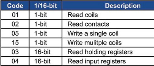
What do you get when you read register 33094 with the modbus master simulator progarm?
How certain are you that Dr. Coghlan’s document is valid for the inverter you have?
The results you’re getting suggest it might not be.
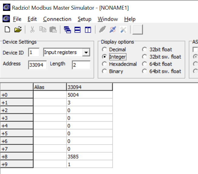
Yep. Dead on the money.
So that means you should be able to read it via Python and MM with the read_reg function.
(that’s the function selected by the app’s Integer bullet)
I’d say that’s a fair assessment.
I’ve been using minimalmodbus for about 4 years. (started with version 0.6)
Haven’t had any problems reading modbus based energy meters from 3 different manufacturers.
(Elkor WattsOn, Continental Control Systems WattNode, Peacefair (cheap Chinese) PZEM-016.
So I’m a bit puzzled as to why it’s not working for you ATM.
Looking at the python code I grabbed from the github above, it seems like it is written for an older version of minimalmodbus:
Realtime_DCV = instrument.read_register(33021, numberOfDecimals=0, functioncode=4, signed=False)
And from the api docs:
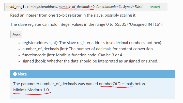
There may be other syntax issues like this (though it still executed even with numberOfDecimals instead of number_of_decimals) so I will try and go through and validate it against latest version of minimalmodbus first.
The breaking changes shown on the MM history page at:
https://minimalmodbus.readthedocs.io/en/stable/history.html
include:
Release 1.0.0 (2019-08-10)
- Renamed method arguments ‘numberOfDecimals’, ‘numberOfRegisters’ to ‘number_of_decimals’, ‘number_of_registers’
- Removed example drivers for Eurotherm 3500 and Omegacn 7500, as I no longer have access to these instruments for testing. It would great if someone would pick up support for these instruments in a separate project.
- Requires pyserial 3.0 or later.
- Removed module level constants for default values, as they were confusingly named.
The rest of that page doesn’t show any other breaking changes.
I don’t know if this will help any, but here’s the Python sketch I use to read my WattNode:
wn.zip (2.0 KB)
Thanks for that might help to compare.
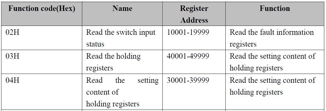
Also got the official modbus docs from the manufacturer so it seems like the register numbers are more or less the same as the unofficial doc.
Attaching here as it might help someone.
RS485_MODBUS (ESINV-33000ID) Hybrid Inverter_.zip (370.0 KB)
Edit - renamed attachment to match document title - Moderator
One question, I will be connecting both the official wifi logger and my usb adapter to the inverter at the same time so I can continue to use both.
Do I need to change instrument = minimalmodbus.Instrument('/dev/ttyUSB0', 1) to something like instrument = minimalmodbus.Instrument('/dev/ttyUSB0', 2) ? Or what’s the correct way to do it?
As long as the two devices have unique addresses, it should work.
Valid addresses range from 1 to 247.
You’ve got it. That’s the way to do it.
Don’t forget to do whatever is necessary to change the device’s address. ![]()
Looks like the manual is translation from Chinese so I am not 100% sure it is translated correctly, lost in translation and all that.
Hopefully I get a bit of time to test things out today ![]()
Some progress.
I am able to read the modbus registers directly from Home Assistant using the usb rs485 cable but I have come across a new issue.
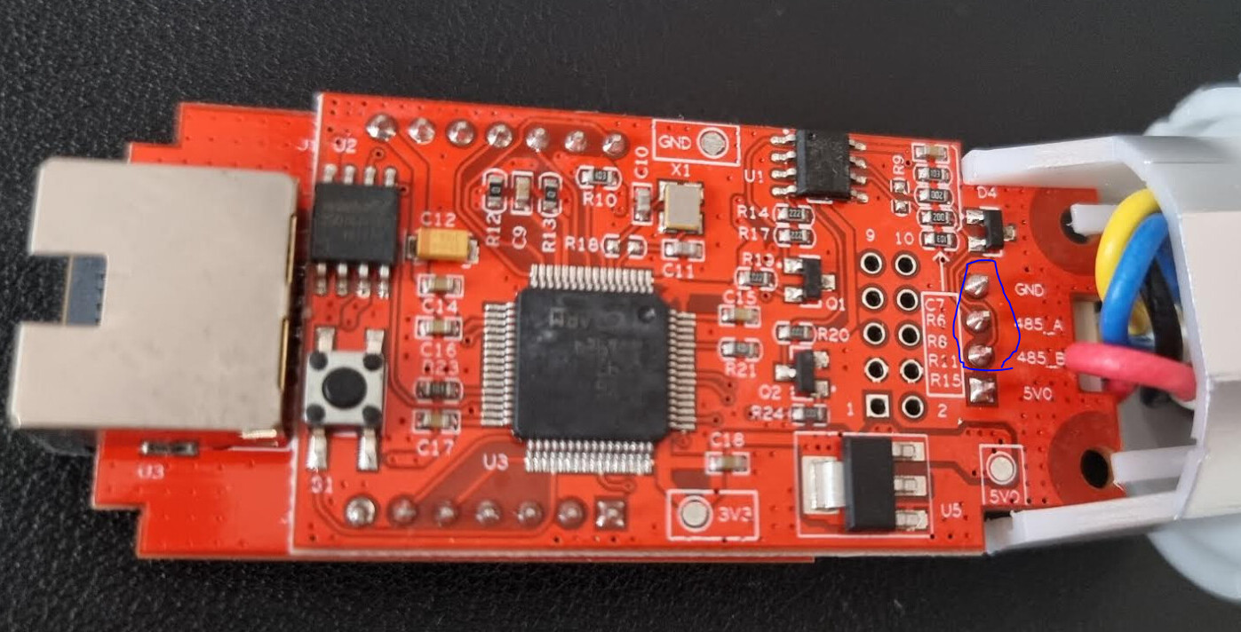
I have connected my rs485 adapter cable to the A/B/GND pins of the wifi logger so they are both connected to the inverter at the same time which should be fine in theory but I think they are tripping over each other.
Sometimes as I can see the logger log some crazy values like this:
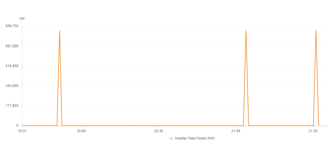
And I am pretty sure I’m not using as much power as a small city

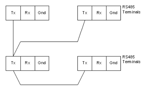
Is the connection A → A, B → B correct (Logger → rs485 adapter)? Or to connect the slaves in series you need something like A → B, B → A?
Yes, that’s correct.
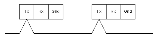
Connect them daisy chain vice star. Avoid the use of stubs (2nd drawing below) if possible.
i.e. like this:
(only the transmit conductor is shown to keep the drawings uncluttered)
not like this:
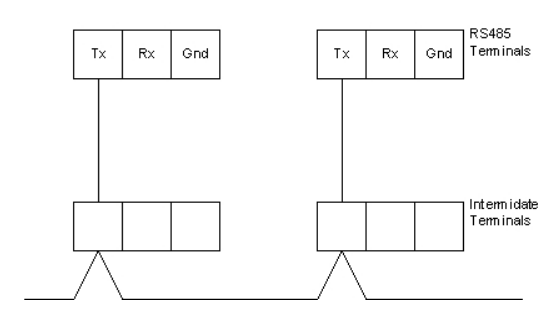
nor this:
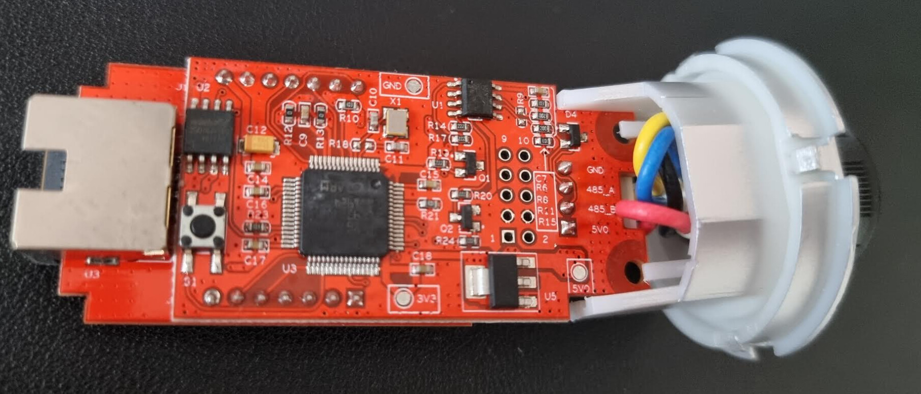
Where do you have the RS485-USB adapter connected?
Yes, the right side is the port that plugs into the inverter so I have piggy backed off of it I guess
That should be OK.
Do you know if the datalogger has a built-in terminator resistor?