Ok not getting anywhere with the new adapter either, same error:
MinimalModbus debug mode. Create serial port /dev/ttyUSB0
here 0
MinimalModbus debug mode. Will write to instrument (expecting 9 bytes back): '\n\x04\x0b¼\x00\x02³p' (0A 04 0B BC 00 02 B3 70)
MinimalModbus debug mode. Clearing serial buffers for port /dev/ttyUSB0
MinimalModbus debug mode. No sleep required before write. Time since previous read: 999826.58 ms, minimum silent period: 4.01 ms.
MinimalModbus debug mode. Response from instrument: '' () (0 bytes), roundtrip time: 201.7 ms. Timeout for reading: 200.0 ms.
That is form pi zero python code.
Code:
import minimalmodbus
import socket
import serial

###		PROGRAM FLOW:
###			- Collect Data from Solis-4G inverter
###			- Convert to individual bytes
###			- Construct 2 messages
###				- KWH Totals only sent when inverter is running, so they are not reset to zero
###				- All other 'live' data set to zero when inverter shuts down
###			- Send Packets to EMONHUB
###
###		EmonHub Node IDs:
###			- NodeID 3: All time energy KWH	/ Today KWH (not sent overnight)
###			- NodeID 4: Live Data Readings - Zeros sent overnight


### COLLECT DATA FROM SOLIS-4G INVERTER ###

instrument = minimalmodbus.Instrument('/dev/ttyUSB0', 10, debug = True) # port name, slave address

instrument.serial.baudrate = 9600   # Baud
instrument.serial.bytesize = 8
instrument.serial.parity   = serial.PARITY_NONE
instrument.serial.stopbits = 1
instrument.serial.timeout  = 0.2   # seconds

success = False # Intialise Success/Failure Flag to ensure full data is only uploaded if all data is received.

try:
	print("here 0")
	Realtime_ACW = instrument.read_long(3004, functioncode=4, signed=False)	#Read AC Watts as Unsigned 32-Bit
	print("here 1")
	Realtime_DCV = instrument.read_register(3021, numberOfDecimals=0, functioncode=4, signed=False) #Read DC Volts as Unsigned 16-Bit
	Realtime_DCI = instrument.read_register(3022, numberOfDecimals=0, functioncode=4, signed=False) #Read DC Current as Unsigned 16-Bit
	Realtime_ACV = instrument.read_register(3035, numberOfDecimals=0, functioncode=4, signed=False) #Read AC Volts as Unsigned 16-Bit
	Realtime_ACI = instrument.read_register(3038, numberOfDecimals=0, functioncode=4, signed=False) #Read AC Current as Unsigned 16-Bit
	Realtime_ACF = instrument.read_register(3042, numberOfDecimals=0, functioncode=4, signed=False) #Read AC Frequency as Unsigned 16-Bit
	Inverter_C = instrument.read_register(3041, numberOfDecimals=0, functioncode=4, signed=True) #Read Inverter Temperature as Signed 16-Bit

	AlltimeEnergy_KW = instrument.read_long(3008, functioncode=4, signed=False) # Read All Time Energy (KWH Total) as Unsigned 32-Bit
	Today_KW = instrument.read_register(3014, numberOfDecimals=0, functioncode=4, signed=False) # Read Today Energy (KWH Total) as 16-Bit

	##Convert Data to Bytes
	A1 = Realtime_ACW % 256
	A2 = (Realtime_ACW >> 8) % 256
	A3 = (Realtime_ACW >> 16) % 256
	A4 = (Realtime_ACW >> 24) % 256

	B1 = AlltimeEnergy_KW % 256
	B2 = (AlltimeEnergy_KW >> 8) % 256
	B3 = (AlltimeEnergy_KW >> 16) % 256
	B4 = (AlltimeEnergy_KW >> 24) % 256

	C1 = Today_KW % 256
	C2 = (Today_KW >> 8) % 256

	D1 = Realtime_DCV % 256
	D2 = (Realtime_DCV >> 8) % 256

	E1 = Realtime_DCI % 256
	E2 = (Realtime_DCI >> 8) % 256

	F1 = Inverter_C % 256
	F2 = (Inverter_C >> 8) % 256

	G1 = Realtime_ACF % 256
	G2 = (Realtime_ACF >> 8) % 256

	H1 = Realtime_ACV % 256
	H2 = (Realtime_ACV >> 8) % 256

	I1 = Realtime_ACI % 256
	I2 = (Realtime_ACI >> 8) % 256

    ##Flag to stream all data to EmonHub
	success = True

except:
	##EXCEPTION WILL OCCUR WHEN INVERTER SHUTS DOWN WHEN PANELS ARE OFF

	A1 = 0
	A2 = 0
	A3 = 0
	A4 = 0

	## Not sent when inverter turns off
	## B1 = 0
	## B2 = 0
	## B3 = 0
	## B4 = 0

	## C1 = 0
	## C2 = 0
	## END NOT SENT WHEN INVERTER TURNS OFF

	D1 = 0
	D2 = 0

	E1 = 0
	E2 = 0

	F1 = 0
	F2 = 0

	G1 = 0
	G2 = 0

	H1 = 0
	H2 = 0

	I1 = 0
	I2 = 0

	print("inside exception")
	##Flag to stream restricted data to EmonHub
	success = False

### END COLLECT DATA FROM SOLIS-4G INVERTER ###


### STREAM RESULT TO EMONHUB ###
#s = socket.socket(socket.AF_INET, socket.SOCK_STREAM) #Initialise Socket
#s.connect(('192.168.0.238', 8123)) #Connect to Local EmonHub

## NOT SENT WHEN INVERTER TURNS OFF
#if success == True:
#	s.sendall('03 ' + str(B1) + ' ' + str(B2) + ' ' + str(B3) + ' ' + str(B4) + ' ' + str(C1) + ' ' + str(C2) + '\r\n')

#s.sendall('04 ' + str(A1) + ' ' + str(A2) + ' ' + str(A3) + ' ' + str(A4) + ' ' + str(D1) + ' ' + str(D2) + ' ' + str(E1) + ' ' + str(E2) + ' ' + str(F1) + ' ' + str(F2) + ' ' + str(G1) + ' ' + str(G2) + ' ' + str(H1) + ' ' + str(H2) + ' ' + str(I1) + ' ' + str(I2) + '\r\n')
#s.close()
### END SEND TO EMON HUB #
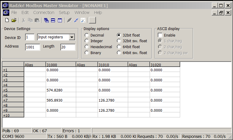
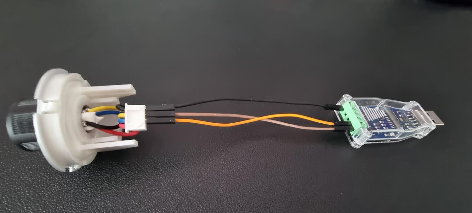
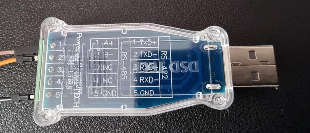
Either the code is no good for a Solis 5G inverter or the adapter/pi doesn’t work or the wiring is not right but it’s hard to get wrong the wiring, pins 3 and 4 on the inverter and A and B on the usb adapter (tried the other way around just in case)
I wish I had a way to confirm that the adapter actually works right or get some sort of response from the inverter