Hah. Sorted it. The earth wire was the problem. I think I connected it to something that wasn’t actually earthed. D’oh!
That and swapping the cables over between + and - fixed it. I did try both ways round multiple times, and assumed the ‘wrong’ way around was the correct way since that was the only way I got any data from it. But it works now. Yippee!
Sweet, if you can share that diagram it would be great.
And another question, can you obtain live data with the piggyback method when it’s both sending to Solis and to the rpi or do you only get the data when it actually sends it to the cloud, every 5-6 mins?
Yes you have live data - You have to set yourself a Modbus address (the inverters can only be address 1) so set yourself somthing like address 10.
Modbus is a shared bus - so you can continually poll the inverter (say every 10 seconds) - occasionally you will get a collision with the WIFI dongle but they will both recover.
The WIFI dongle will continue to do its thing and send data to the cloud and you can log all your data locally.
Perfect, thanks for confirming.
And how do you pull the data? USB to rs485 cable directly to Home Assistant and then just add the modbus integration or wire the cable to another device/raspberry pi and have that read the data with python and then sending to Home Assistant?
The way i get the data is to read it into Node Red, i then use that to pump it out to an Influx database and for other home automation things - you could obviously send it from Node Red through MQTT into Home Assistant if that is where you choose to present the information.
Ok I have set up a pi zero with ethernet hat and pi RS485 HAT along with the lite OS and connected it to the inverter logger port.
How can I do a quick test to see if I can obtain some data, any python modbus code someone can share so that I can prove it is working?
Thanks in advance
Guys I need a hand, cannot get any data back from the modbus script.
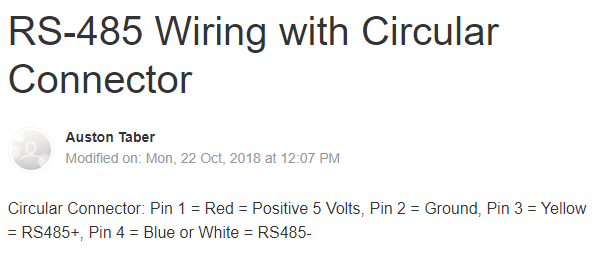
I have a pi zero connected to one of these FTDI usb cables and then connected to the Solis inverter pins as follows:
Pin 2 GND
Pin 3 A
Pin 4 B
I have been testing with raspberry pi OS and Thonny for running the python script but not getting anything back (tried reversing the A and B wires just in case and still nothing)
I am testing with @Ian999 's code from rogersia/Solis-4G
My inverter is a 5G 6kw Hybrid so maybe it just doesn’t work? Has anyone had any success with a 5G yet?
Is there some sort of small script I can use to verify that my connection is correct? Even if there’s a Windows app I can quickly try with my laptop
That adapter is NOT a rs485 adapter so it won’t work. You are on the right track to try a simple rs485 usb adapter rather than the Pi Hat you linked in the previous post. Those hats are troublesome to get working so you are right to get everything else in place (using a simpler adapter) before trying to get that working. Use something like this
Then use some of the code from that script to test step by step if it doesn’t work out of the box.
Just adding lots of print statements to the code temporarily whilst starting it from the command line will give you useful feedback, also look at the minimalmodbus library as the connection command could be altered to include debug=true which gives a lot of feedback as to the connection and data transactions, if there are any.
It’s always difficult to debug with someone elses finished script as they tend to work or not, thers’s rarely any error messages or assistance when it doesn’t work.
If you have your docs for the inverter it may give examples of what to send to get a response, looking at the minimalmodbus examples too, you should be able to get a small test transaction to work, but no it’s unlikely someone will have one to hand as that is where all finished scripts start so the basic stuff gets lost along the way. Doing it from scratch will give you a better understanding and actually be easier to debug than trying to guess why a finished script won’t entirely complete without any clues.
So I purchased the same chip ft232rl as Ian did in an early post above which works ok for him on a pi?
I do have the rs485 pi hat also and same thing there.
How about this one, the one you linked doesn’t ship to my address.
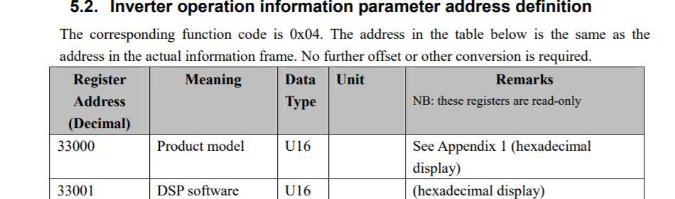
Yup that is what I have been doing but it seems to error as soon as it tries to hit this line: Realtime_ACW = instrument.read_long(3004, functioncode=4, signed=False) #Read AC Watts as Unsigned 32-Bit
Will try debug also.
Unfortunately not, the only thing that came close to a doc was this pdf, which is not official and I am not sure how to run the commands in there.
The FTDI FT232RL Chipset is a very versatile chip used for many serial applications, you need rs485 the one you are trying to use currently is basically a modern usb rs232 “serial port” albeit a lower voltage IIRC, but the same protocols ie not rs485.
You were never going to get a connection with the current adapter and the hat will need some trial and error, plus some additional code probably. So ignore what has happened thus far and try again with the basic rs485 adapter. Use debug=true and run the script/command in such away that you can see the output.
Looking at the script it seems the connection is attempted but no provision is made for failure, it just moves straight into try reading, so if it cannot read, that may be because the connection failed, I would not be surprised if you got the same response with no wire attached to the adapter at all, don’t forget there are 2 connections inline, Pi to adapter and adapter to inverter, connecting to the adapter and setting the baud etc, doesn’t mean the adapter is connecting to the inverter. In your latter tests the adapter to inverter bit wouldn’t have worked as it’s the wrong adapter, hence tripping up at the read part.
Thanks for the tip, I will go ahead and buy that other adapter which you have mentioned and I can try again with this one RS485 CAN HAT - Waveshare Wiki since I still have it around.
This is what I got with that ftdi cable and debug:
MinimalModbus debug mode. Create serial port /dev/ttyUSB0
here 0
MinimalModbus debug mode. Will write to instrument (expecting 9 bytes back): '\n\x04\x0b¼\x00\x02³p' (0A 04 0B BC 00 02 B3 70)
MinimalModbus debug mode. Clearing serial buffers for port /dev/ttyUSB0
MinimalModbus debug mode. No sleep required before write. Time since previous read: 252240.93 ms, minimum silent period: 4.01 ms.
MinimalModbus debug mode. Response from instrument: '\n\x04\x0b¼\x00\x02³p' (0A 04 0B BC 00 02 B3 70) (8 bytes), roundtrip time: 203.7 ms. Timeout for reading: 200.0 ms.
Yeah I think that’s just jibberish. The minimalmodbus prints are standard text messages and the “data” shown is just some traffic it recieved, it is not interacting. If you look at that doc you linked there are some examples and if you note all Tx and RX transactions start with the device ID and transation type, you are trying to send id 1 type 4 and so any valid response would start the same eg from that doc
I have yet to find a modbus device that doesn’t work with just the 2 connections.
Whilst rs485 is a 2 wire protocol there is ref to the 3rd connection in the spec and you will find arguments both for and against, both here on the forum and the wider web.
I would assume something like the inverter logger sticks need it because they are being powered by the inverter but it makes sense that you don’t when you already have power/gnd from the USB port on the rs485 adapter.
Any windows apps that you can suggest which I can use to test the new adapter when it arrives? Once I know it works I can move it to the pi zero
TBH No, I’ve not tried any windows apps for modbus specifically. I guess there must be some like Postman for http and MQTTLens for MQTT etc. I guess you could most probably just use Putty?
However, unless you find a simple test app, I wouldn’t bother connecting it to the PC, the drivers may be different to linux and unless you have Python installed already on the PC you are better off just using Putty to SSH and work via your PC whilst the adapter and code are on the Pi. With a encrypted private/public key set up (using pageant, comes with putty for windows) it’s as easy as opening a window on your PC, assuming they are on the same LAN.
Wouldn’t the 1.5 character and 3.5 character time limits make generating a poll with puTTY a no-go?
(although one could monitor the bus with puTTY if a master is present)
In RTU mode, messages start with a silent interval of at least 3.5 character times. This is most easily implemented as a multiple of character times at the baud rate that is being used on the network (shown as T1-T2-T3-T4 in the figure below). The first field then transmitted is the device address. The allowable characters transmitted for all fields are hexadecimal 0 … 9, A … F. Networked devices monitor the network bus continuously, including during the silent intervals. When the first field (the address field) is received, each device decodes it to find out if it is the addressed device. Following the last transmitted character, a similar interval of at least 3.5 character times marks the end of the message. A new message can begin after this interval. The entire message frame must be transmitted as a continuous stream. If a silent interval of more than 1.5 character times occurs before completion of the frame, the receiving device flushes the incomplete message and assumes that the next byte will be the address field of a new message. Similarly, if a new message begins earlier than 3.5 character times following a previous message, the receiving device will consider it a continuation of the previous message. This will set an error, as the value in the final CRC field will not be valid for the combined messages. A typical message frame is shown below.
Start
Address
Function
Data
CRC
End
3.5 Char time
8 Bit
8 Bit
N * 8Bit
16 Bit
3.5 Char time
The adapter you linked to is supported by Windows directly. i.e. no drivers needed.
I’ve got four of them and have used them on XP, 7 and 10 with no issues.
I really have no idea, never thought about it much. TBH if you have putty installed I would move swiftly to SSH with the USB adapter in the PI, unless you already have Python and relevant packages already installed. I do a lot of dev work on a PC but I wouldn’t install anything or set up a dev environment just to test something that was moving to a Pi when it’s so easy to remotely access the Pi directly from the start.
Yeah I have many of them too and haven’t had any troubles I can recall, but I wasn’t sure if I had or hadn’t installed drivers at some point in the past. My point being, even if the script/dongle/device combo works on windows, it might not guarantee it working on linux/Rpi so it can be misleading to test it on different architecture/OS etc, sometimes it’s useful, especially when you’re all set up for it and have experience with the parts in question, but trying to figure out something new on multiple platforms when you have no proven “known good” parts could be somewhat confusing.
Ok got the adapter just now, next need to test it out.
That modbus simulator app from above does what exactly? It says modbus master simulator
Ideally I would want to run this on my windows laptop and connect to the inverter using the usb rs485 adapter but not sure if this will work since I need to connect as slave?