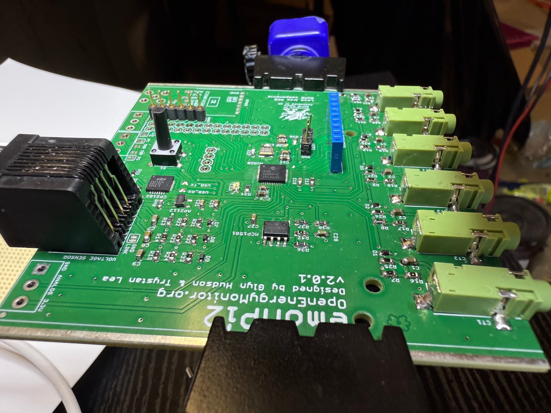
Hello! I have admired this project for many years and really appreciate the documentation that is provided. I decided to actually mix a couple of my hobbies together to see if I could manufacture an emonpi2 and do the micro-soldering and then monitor my house’s power usage. I’ve had a PCB manufacturer create 5 copies of the emonpi2 board and expansion board for me, I created a bill of materials and purchased everything from Mouser.com and I’ve populated all of the components that I think I need. I figured out how to flash the bootloader via UPDI, and I’ve compiled the emonpi2 software.
It’s running! And I’m so happy that I’ve made it this far. But the emonpi2 won’t actually PRINT anything to the serial console unless it detects an AC signal on VSENSE1. I did not make the emonVs, so I’m trying to figure out how to create the ACAC Converter board. I’ve found this documentation that relates to the emonTx4 and was wondering if something similar could work for me?
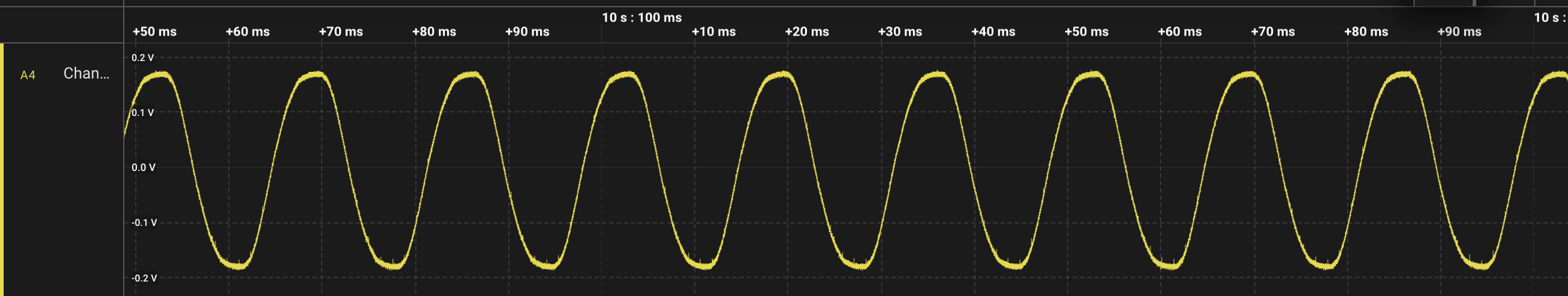
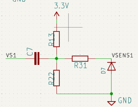
At the bottom, it shows an AC adapter going through 2 resistors and into an RJ11 jack. I’ve tried to make a voltage bias circuit to get me down to 0.333 V RMS, but it doesn’t seem to work. I read some documentation somewhere about how I should aim for 0.166V RMS since I am in North America and I have 120V AC. When I hook a logic analyzer up to it and measure at R31, I see that my AC signal is there, but it’s range is -0.166 to 0.166 and it is not being shifted up.
I’ve tried tweaking the circuit on the emonpi2 to not be 120kOhm / 33kOhm bias, but make it 120k/120k to get it to bring the signal up to 1.65V, but it didn’t work.
Does anyone have any suggestions on what approach I can look to take next?
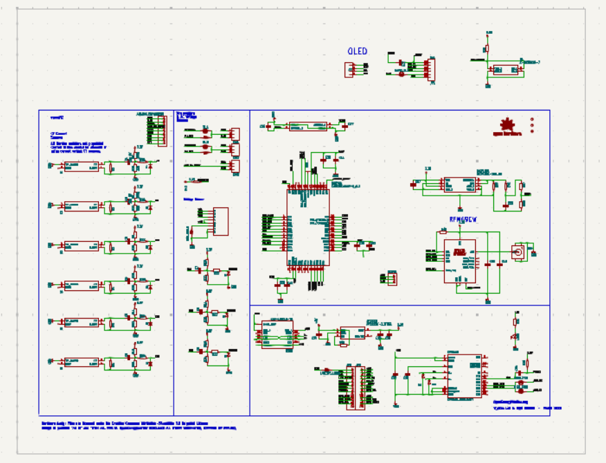
I don’t understand what you’ve actually made - is it the electrical energy monitoring “front end” which piggy-backs on a Raspberry Pi? and if so, how much of it have you constructed? You should have almost everything on here - but you only need 2 voltage inputs for a N.America split supply, and you might not want the radio.
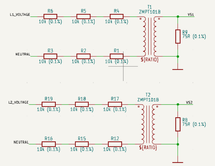
Only the emonVs made it into production, so copying the voltage sensing part of this will work. What you need is just two voltage sections from the emonVs (one for each leg of your split supply):
The AVR-DB ADC is set up to have a 0 – 1.024 V input range. If, with nothing connected to the ‘free’ end of C7 (VS1), R31 isn’t sitting at about 0.512 V d.c, (NOT 1.65 V which is for the ATMega/Arduino processor) the fault lies in the 3.3 V supply to R13, one of the components here or the track VSENSE1 to the AVR-DB processor.
When you connect C7 (VS1) to the c.t. burden (R9) the d.c. level should not change.
Then, when you apply 120 V between L1_VOLTAGE and NEUTRAL, you should see about 150 mV rms (425 mV peak-peak) across R9 and the same at VSENSE1 but sitting on the 500 mV d.c (so swinging between 287 mV and 712 mV approximately).
Note that the 6 resistors are essential for safety - so that the voltage applied across any single resistor is well below its voltage rating - and your PCB tracks must be spaced for the full 350 V peak open-circuit voltage should one resistor fail open-circuit. If you don’t change the values, you can safely measure your 240 V if you’re so inclined.
I didn’t populate the radio section, but everything else is populated.
I verified at R13, and I have 3.3V on one side. At R31 with nothing connected, I have 8.7mv, so there is definitely something wrong. It may well be the connection to the AVRDB128, as I am not very happy with how I soldered it. I’ll try to fix that up and see if it improves.
I also can’t get my 12 Mhz crystal working. I think I may have cooked it when trying to solder it on. So it’s using the internal clock which I understand to be inferior.
Thank you for the circuit diagram for measuring the voltage. I’ll order some parts and construct that, and also try resoldering the AVRDB128.
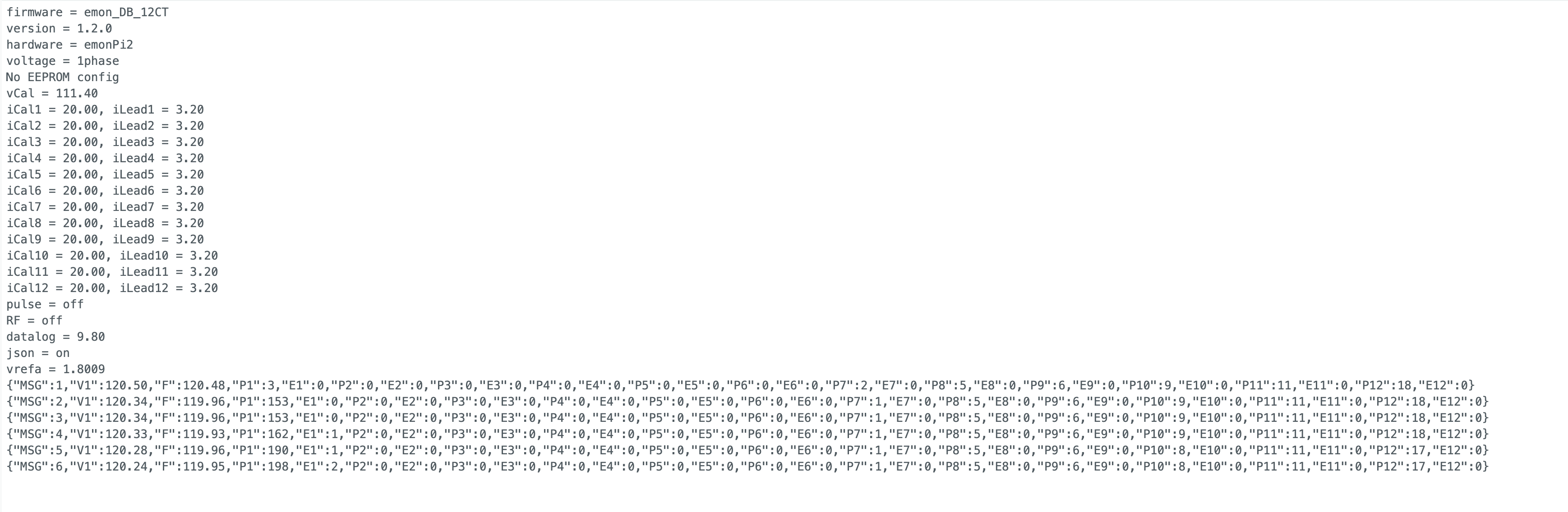
Hooray! I got it to work! I re-soldered the AVRDB128 but the VSENSE1 circuit is still wrong with no voltage at R31, but VSENSE2 and VSENSE3 are both centered around 0.5V as you said they should be, so I modified the ADCPin mapping in the emonDBLib to use VSENSE2 to detect AC instead and it started working.
Thank you so much for your help. I bought enough parts to build another one so that I can monitor all of the individual the circuits in my house, so hopefully VSENSE1 will work properly on that board. I really think it’s due to my poor soldering job.