so, on the first view it looks very good.
On peak power of the PV inverter (there is constant power out 4100W) I see a deviation on only 0,8%.
Yesterday I saw a bigger failure on low power (<100W). So I will check the daily deviation first for total house energy(P1-P3) and PV, compared to the grid counter and then will try to get the average matched to my meter.
By the way, I found a cheap second hand TDC 9V AC (09-06) on ebay. I bought it and will check if with this one will behave more, than expected. As written, I use now vcal : 245, so maybe, my idealpower is not OK.
You must expect that. Current transformers are inherently less accurate at low currents, add to that the errors in the analogue to digital conversion.
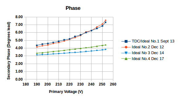
You can read my test report of two Ideal/TDC a.c. adapters (UK version) in the ‘Learn’ section. The Euro version is a different voltage ratio, but otherwise I assume its properties will be very similar. I recently tested some later units and found significant differences in the phase error.
Of course, I already read your report!
Btw, 1 day:
PV:            Solar rectifier:  21,7kWh   emonTX: 21,562kWh   >> -0,6%
Energy(2,5h):     grid counter:   1,7kWh   emonTX:  1,697kWh   >> -0,2%
This is without CT calibration and awsome!
Edited post for readability - BT
1 Like
Bill, thank you for the readability pimp! I am struggeling with this editor.
But, as you are from USA: what is your problem with “f…” awsome?
The way you wrote the expression, the first word that will come to mind for many is one that’s considered
to be profanity. Since anyone (e.g. women and minors) could be reading the forum posts, we keep it “clean.”
It’s great that you have everything up and running and have already modified the firmware yourself. As you have noticed, with the emontx a lot is possible, but it’s not really plug and play yet, that’s more the approach of IotaWatt. @Robert.Wall made a very good suggestion (called unitless firmware), which would give the plug and play approach a huge boost, I hope that this will be implemented sometime.
As @Robert.Wall already mentioned, you could have switched the DIP switch in the device for the calibration factors for the EU voltage transformer instead of changing the firmware. But since you had to change the firmware anyway because of the change for input 4, this would not have been an advantage.
The emontx should run without the 5V USB power supply. I have here a device that runs since March 26 without a single reboot and is connected only with the voltage transformer. However, the mains voltage has not fallen below 228 V during this time. At lower voltages a reboot can take place, because then the power is not sufficient. Therefore it would be interesting to know what voltage you are measuring with an external multimeter at times when the emontx is continuously restarted if it is only connected via the voltage transformer.
Hi Simsala,
it was a chalenge for me to bring the emonTX to life but now I am proud to have done this.
I am a electrical engineer with some SW experience but it was not easy for me, to find the necessary inputs to get it running.
Robert was clearly a key for me, but “normal” customers wil faill with this (IMHO).
My DIP switch is set to EU but I had to make a significant decrease to the vcal to have it fitting (245,2).
228 V is (I can not use the f word) very close to the 230V, we have here in Germany. On sunny days, mains voltage maybe 232V and more but at the end of daylight, it often goes below 228V temporarily.
I have a calibrated Fluke 89 IV and so measure correct values.
At the moment, I am happy, to have th emonTX powered by USB and it works.
As written, I am realy impressed of the accuracy.
If interesting for this project, I can go back to AC powering and check, what happens.
That description could just as well apply to me.
I understand what you’re saying there. Maybe points like this can be addressed if the STM32 development project comes about, because the additional processing power should make it much easier to implement advanced functions and a more user-friendly approach. As it is, this sketch is running very close to the limits of what the Atmel 328P can do. It has very limited facilities for interacting with the user, as you have found out, and it’s very difficult to anticipate all the variations that are possible, and arrange for those to be selected at run-time.
I’m sorry, that wasn’t clear here: I’m not saying that there are reboots below 228 V, only that the mains voltage here hasn’t dropped lower in the last three months and no reboots have taken place during that time. So far I cannot say where the limit lies.
Ah yes I see that vcal_EU was reset to 260. I had suggested a value of 248 in a pull request, so a similar value as you found out during the calibration. @Robert.Wall do you know why the value was reset? 260 is far too high for the EU voltage transformer.
yesterday(sunday) at 9:30am I measured 226.1 V here
The transformer voltage is 11.5 V for 230 V input, the voltage divider in the emonTx V3.4. is 10 kΩ & 120 kΩ, so 13:1, therefore for 1 V out of the divider, you need 13 × 230 ÷ 11.5 = 260 V. If the transformer no-load voltage has changed, nobody has told me.
[@Gwil - can you check with Ideal? 77DE-06-09-MI, creation date Fri 22 Nov 2013 10:21:06 GMT ]
But you put the sketch on Github, I have had nothing to do with it since I sent it to you. So my guess is, you always set the calibration in EEPROM and did not change the sketch?
Thanks for your answer, looks like @glyn.hudson accidentally changed that: v1.2 temp error codes by RW · openenergymonitor/emontx-3phase@e70f1b9 · GitHub
@glyn.hudson can you please undo this or determine good calibration values for the EU transformer? It would also be nice if the suitable calibration values for the ordered EU voltage transformers could be set directly before the orders are shipped.
I will check my transformer no load voltage next time, I have to unplug it.
Maybe this evening, when I calibrate the ICALs.
Therefore I assume that theese factors are (more or less) linear.
That means (e.g.), if I measure a failure of -1% I change IxCAL to 90.91/0.99 = 91.82?
(Maybe this needs iteration steps.)
Or am I completely wrong?
I measured the open circuit voltage, it’s 12.2V, so it follows: 13 × 230 ÷ 12.2 = 245.08 for vcal_EU. @laun3006 Exactly the value you determined experimentally, very good!
Update: I made another measurement (I only have one good multimeter at hand, so unfortunately I can’t measure it exactly at the same time). The mains voltage is now at around 235 and the open circuit voltage of the transformer: 12.4. 13 × 235 ÷ 12.4 = 246.4
Update2: I measured other voltage transformers of this model: 246.3 (13 × 234 ÷ 12,35). I made a mistake during the first measurement because the voltage was not measured on the primary side. However, the correct measurements always result in about 246.
If you look at my earlier post mentioning phase errors (Nr.42), it appears that there have been changes in the materials for the UK version - that’s what made me suggest that there might have been a change in manufacture of the EU version, which we haven’t been told about.
All the more reason (while we still have the ATMega 328P, though this might change with the STM) for a “unitless” library, “unitless” sketches and having all the calibration in one place - in emonHub or emonCMS. But the cost is more data needs to be sent (if you do the phase calibration there too - and it is silly not to).
1 Like
Correct - while the fraction is close to unity, of course! Vcal & Ical are simply constant multipliers in the maths. But it obviously is not true with a larger error, so if you read 1.2 × the correct value, you change the multiplier to Ical ÷ 1.2, or Ical × 0.8333, and not Ical × 0.8 .
(OK, I know you’re an engineer and would not make that mistake, but someone else reading this later might.)
A silly point to mention - In the emonTx, power is calculated using both Ical & Vcal.
But if you calibrate in emonHub, you must change both voltage and power scales = factors because the power and voltage are independent when they reach emonHub.
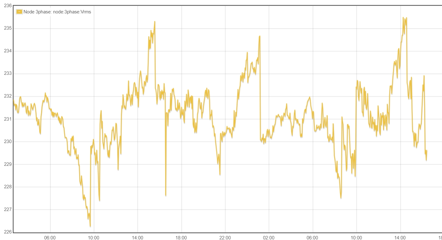
Uploaded picture shows the grid quality (Vrms) at my home the last 2 days. It is from 226.3V (yesterday, 9:30am) to 235.5V (today 14:00). First reason is PV and Wind generated energy. But for me very interesting is the step last night at 1.10am. A spontaneus decrease from 234.6V to 230V. Looks like a bigger switch in the grid. Thanks to openenergymonitor, I see it now.
This is a ±2% variance on the mains and therefore, Vrms tracking is very helpfull.
(The needle at 16:30 yesterday may be forced by me. This should have been a short unplug/plug by myselve)
That is a good indication of when the system is under load (and the voltage falls) and not (the voltage rises). Here in the UK, because we are not locked to the European grid, frequency is a much better indicator of the loading nationally. In the late evening, the frequency rises, then the grid controller will tell a power station to shut down, and the frequency falls rapidly as there is now less generation capacity. And so it goes on, usually in 4 or 5 steps, until everything settles. Then in the morning, the reverse happens as load increases as people wake up and go to work.
Frequency deviation is very low here. I normaly see 49.98 - 50.02 Hz. Is it possible to read out frequency from the emonTX? I would like to trace it, too. I could kill rssi because I dont need it.
Maybe, I find a way?