Germany 3+N Household with additional 1Phase PV and planned EV Car

(Line numbers are my original sketch - it appears that Glyn has changed things, so they are probably wrong, but somewhere near.)

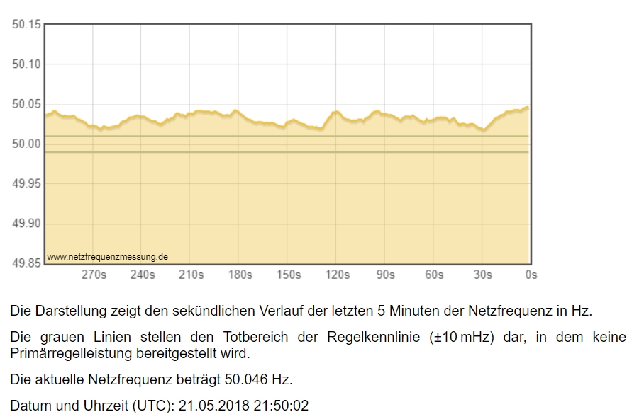
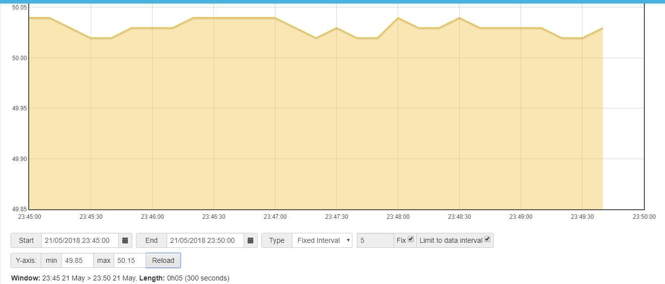
You (?) should be able to get the sketch to tell you frequency - subject of course to the accuracy of your oscillator. I found I could calibrate that by comparing my record of frequency against the published value.
It is calculated at line 739, printed to your serial monitor, but not sent by radio. (While I remember, the constant 16000000 in there is the nominal oscillator frequency - that’s the number you change to calibrate frequency.)

So what you need to do is, in line 278, add “frequency”. This includes it in the packet of information sent to emonHub:
typedef struct { int power1, power2, power3, power4, Vrms, frequency, temp[MAXONEWIRE] = {UNUSED_TEMPERATURE,UNUSED_TEMPERATURE, UNUSED_TEMPERATURE,UNUSED_TEMPERATURE,UNUSED_TEMPERATURE,UNUSED_TEMPERATURE}; unsigned long pulseCount; } PayloadTx;

After line 804: emontx.Vrms=(int)(Vrms*100+0.5);
add a new line to write the value into that data packet:
emontx.frequency=(int)(frequency*100+0.5);
this will send frequency as an integer ×100, e.g. 5000, giving you a value to within ± 0.005 Hz.

Compile the new sketch and load it into your emonTx. It will stop reporting in your emonBase. You must edit emonhub.conf to tell it what to expect.
Find the entry for your emonTx - it should look like this, taken from the top of the sketch:

    [[11]]
        nodename = emonTx_three_phase
        firmware = three_phase
        hardware = emonTx V3.2/V3.4/Shield
    [[[rx]]]
        names = powerL1, powerL2, powerL3, power4, Vrms, temp1, temp2, temp3, temp4, temp5, temp6, pulsecount
        datacodes = h, h, h, h, h, h, h, h, h, h, h, L
        scales = 1,1,1,1,0.01,0.01,0.01,0.01,0.01,0.01,0.01,1
        units =W,W,W,W,V,C,C,C,C,C,C,p

In the same place in each line, you must add the information emonHub needs:

names = powerL1, powerL2, powerL3, power4, Vrms, frequency, temp1, temp2, temp3, temp4, temp5, temp6, pulsecount
datacodes = h, h, h, h, h, h,   h, h, h, h, h, h, L
scales = 1,1,1,1,0.01, 0.01, 0.01,0.01,0.01,0.01,0.01,0.01,1
units =W,W,W,W,V, Hz, C,C,C,C,C,C,p

Save the file.
You should then be able to select “frequency” as an input to a graph, or a dial or a feedvalue.

I have not done this, but it ought to work. DO keep a copy of the original sketch, in case it all goes wrong.

Wow, you are so great :+1:
I will give it a try and - of course - I keep the original!
Approx 30 years ago, I programmed in Fortran. Later a little C.
Now, it seems this basic knowledge can be a benefit.

Fortan 4 for me - at about the same time - early 1980s.

Dear Robert, I did as you told and it works!!

Together with this I did a small adjust of the Ical’s to 91.55 and 16.75.
This, because the deviation of the PV was - 0.5% and for the energy was -0.7%.
Adjust of the frequency I will do on wednsday because I need my PV inverter for this and it runs only when sun is shining and tomorrow I have to work.

Again I have to thank Robert and have to state that this is realy a great mans toy.:sunglasses:

Could you compare your record of frequency with this? Timeline of the utility frequency: Timeline

This fits very close to what I measure! Where do you measure it?

edit: OK, I see, its not measured by you. but it’s exactly what I measure!

edit2: It seems, I do not have to adjust my frequency :slight_smile:

edit3: They measure in the near of Munich, I am in the near of Nuremberg, distance is 170km.

Please see compare of netzfrequenzmessung compared to my measurement.
Snapshot is made synchroneus but for my is always some seconds late, so approx 20s are missing.
Becuase of 10sec sampling rate there are some differences but you can see that it is very close!


As I understand it, the major part of Western Europe, and some of Eastern Europe, is one linked grid where the same frequency applies to the entire area. Therefore, the frequency you see will be the same as that seen anywhere.

Although the UK transfers power to and from the European grid via several different undersea cables, all the links are d.c, and our mains frequency is independent of yours.

If you wanted more resolution in your data, you could multiply by 500, instead of by 100, and then you would have steps of 0.002 Hz instead of 0.01 Hz. A slightly more complicated way would be to change frequency from a signed integer to an unsigned integer, which you allow a number range 0 - 65535, so you could then multiply by 1000 and have steps of 0.001 Hz. If you would like to do that, I can tell you what you need to change.

Maybe, I stick to the 500 multiplyer. 0.002 should be a sufficient resolution for this. My inverter has only 0.01

Yesterday, I wrote new Ical to EEPROM on the fly.

(Maybe) silly question: are they used for calculation imediately after store or do I have to reboot emonTX first?

The documentation says exactly what happens. (Post no.35)

Robert, I would not have asked if it would realy be described clearly. On extraction is:

When the settings have been saved to EEPROM memory, those
values are read at `each power-up thereafter and override the values in sketch. You can
however choose to restore the default values and erase the EEPROM settings.

Therefore, you have to reboot(for my understanding).

Next extraction is:

If you change one or more of the settings, the change will take effect immediately, or when you
continue (option ‘x’) for the RF configuration commands.

So, does it mean, it still takes effect immediately even after you set “x” and do not use RF configuration commands but Cal commands or is the first extraction the truth?

You may decide by yourselve, if it is realy clear described.
As I work in consumer electronics, I know, that writing user manuals is not the easiest thing, because you have to deal with low knowledged folks like me.

Thanks and dont get me wrong!

edit: if openenergymonitor plans to get closer to the bigger markets(what I hope to happen), there has to be done some work for my opinion. Otherwise it will only adress few insiders.

As I explained earlier, the RF settings and the ‘on-line’ settings are separate.

Is this clearer for the RF configuration commands changed during start-up:

If you change one or more of the settings, the change will take effect when you continue (option ‘x’).

And for the change to the ‘on-line’ settings :

When running, you will not normally see any response to a ‘k’ command, but you will see the displayed values change. You will see confirmation when you save the changes. If you change one or more of the settings, the change will take effect immediately. But if you do not save (‘s’) the changes, the settings will revert to the previous values at the next restart. After you save (‘s’) the settings, the new setting will be used forever, or until changed again.

Unfortunately, the whole package has disappeared onto Github, and I no longer have control over it.

OK, I hope, I got it now, thanks!

Up to now, my thinking was, that RF settings are RFM69CW, RF_422MHZ and RFPWR, only, because they define the physical RF transmission.

But now, it seems, RF settings are all settings, which are in any relation to data, sent over RF.

To be honest, I better will push the reset button every time, I change settings, in future.

thanks again and good night

Here is what I think is the clearest yet :sweat:

For the RF configuration commands changed during start-up, if you change one or more of the settings, the change will take effect when you continue (option ‘x’).

For the settings you change when running, you will not normally see any response to a ‘k’ command, but you will see the displayed values change. You will see confirmation when you save the changes. If you change one or more of the settings, the change will take effect immediately.

Option (‘s’) will save all the changes. If you do not do this, the settings will revert to the previous values at the next restart. After you save (‘s’) the changes, the new settings will be used forever, or until changed again.

If you restore the sketch default values (‘r’ during start-up), the EEPROM data is erased and the sketch restarts immediately, using the values set in the sketch. There is then no means of recovering the EEPROM data.