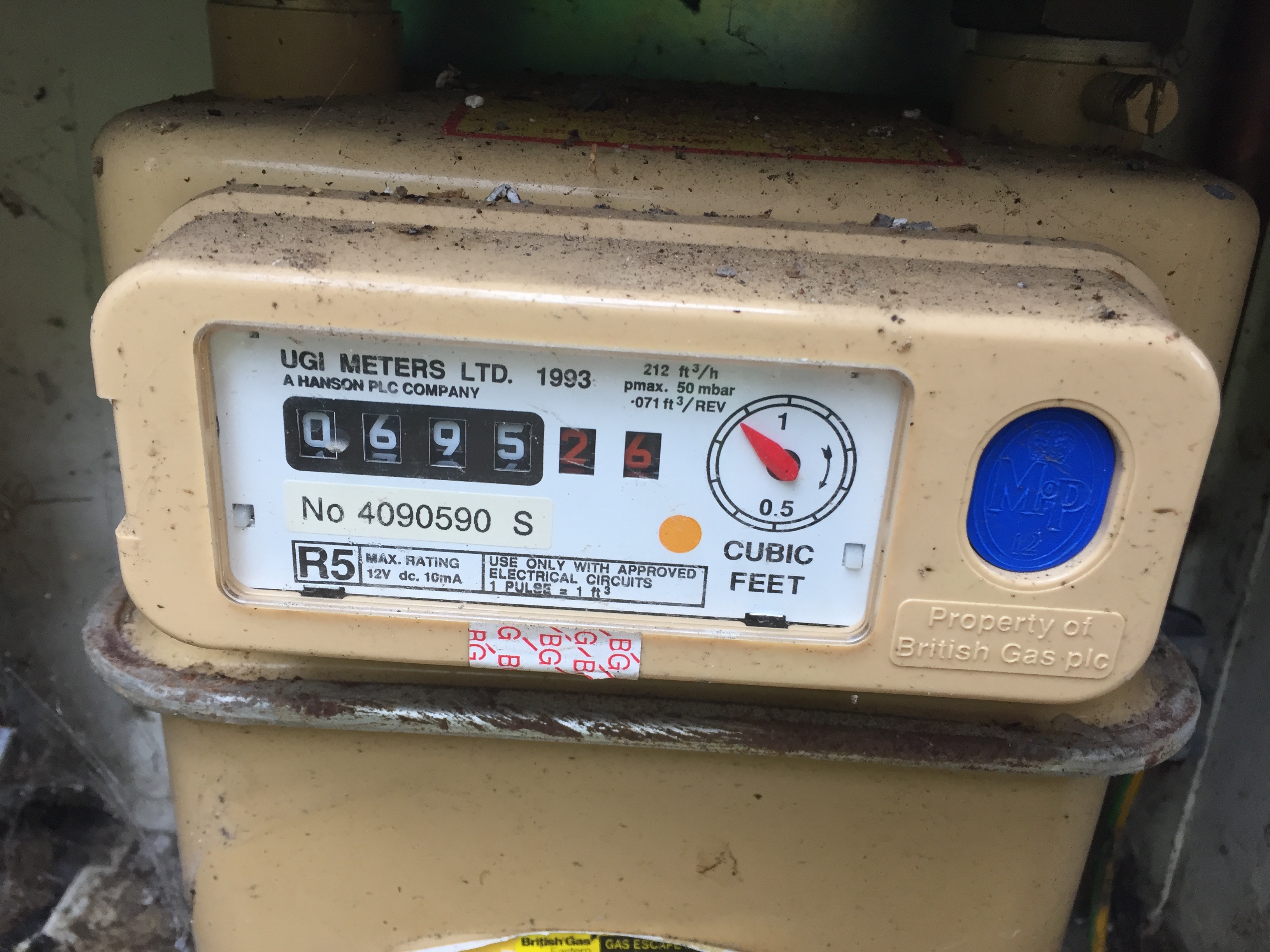
There is a mention on it of “1 pulse = 1 ft^3”, which makes me believe that a pulse counter could work…
However, I’d like to verify that and, if applicable, understand where I should attach the sensor to
I presume there is no obvious connector anywhere? An RJ11 or similar is a favourite. All the markings indicate a pair of contacts will be available somewhere - unless it’s an optional extra that you don’t have. I believe the blue patch is a security seal.
Failing that, the best suggestion is to use a conventional magnetic compass and see it it deflects when held near the 1 ft3 digit. You’ll need watch it for 1 revolution - or check back repeatedly and make sure you haven’t missed the magnet - if there is one. But as I think there is an (optional) internal switch, it’s unlikely there’s a magnet as well.
And similarly, I expect there’s no reflective patch on one of the numerals of the register.
I found a bit more information online actually.
There is a company “saveometer” that has its own product line for monitoring gas and electricity consumption.
I found on their website (thanks, Google!) that they support the R5, and they have instructions online at http://www.saveometer.com/Downloads/Saveometer%20Gas%20Transmitter%20Installation%20Guide.pdf. Reading though this, it appears that there is an RJ11 socket under a tamper-proof sticker. Not sure how I’m going to make use of this information though (electronics and me have never been on the same page…)
Where can I find information about the pulse system on the emonPi or emonTx?
I’m wondering whether I can connect the RJ11 cable directly to the emonTx. The information at EmonTx V3 - OpenEnergyMonitor Wiki seems to indicate this could be done? (again, I’m really not au fait with electronics)
There is a lot of information in the old forums (Archived).
If you really do have a (presumably reed) switch inside your meter, then it’s a case of two wires to the emonTx/emonPi.(You’ll probably have to buy a cable with the RJ11 plug and cut whatever is on the other end off.) If it’s an emonPi, then unless you have the correct cable and crimping tool, you’ll need a RJ45 to screw terminals adapter and a short Ethernet jumper cable. If it’s an emonTx, you can do that or you can use the screw terminal connector that is wired in parallel with the socket.
The standard sketches can already do pulse counting.
Thanks for the help Robert.
I think I get it (mostly).
Could you clarify what you mean by “correct cable”?
I have a few old RJ11 cables lying around (unless I’m mistaken, ADSL routers tended to come with them), however they are all too short for the distance between my gas meter and the emonPi location. Looks like I’m going to have to make one and invest in a crimping tool. Would I be right in thinking that any cable with 3 wires (for pins 2, 5 and 6 on the RJ45 side if I understand correctly) should do?
Also, can I clarify how I should treat the GND pin, given that on the meter side, it appears that there are only 2 pins?
Many thanks (and sorry for the basic questions constantly coming from me - I’m trying to learn as quickly as I can)
One that fits the meter - and uses the correct pins! Unless you can find that information, the only way will be to test with a continuity tester/multimeter and find which pins the switch is wired to. Which 2 pins of course - you don’t need 3 for a switch, just ignore pins/wires that are not used.
What is the distance - a few metres or is it more? If it is more than say 3 m, I would start to think about interference being picked up, especially if the cable will run alongside mains cables, and in that case a twin screened 'microphone '-type cable, using the two inner cores for the switch and earthing the screen, might be a good idea.
If you look at the emonTx sketch, you’ll see the line pinMode(pulse_count_pin, INPUT_PULLUP);
That tells you that the pulse input (on pin 4 of the screw terminals, or pin 6 of the RJ45) should connect to GND (pin 3 on the screw terminals or pin 5 on the RJ45) via the switch in the meter.
According to a couple of old posts (in the old forum and on another website), the RJ11 has only 2 pins wired on 3 & 4.
Can I therefore validate that this would be the correct connection?
I would like to connect directly to the emonPi, I don’t need an additional emonTx at this stage.
Could I validate that I understand correctly that the connection should be as follows?
emonPi RJ45 pin 6 <–> UGC R5 meter RJ11 pin 3
emonPi RJ45 pin 5 <–> UGC R5 meter RJ11 pin 4
Alternatively I understand that the emonTH can also do pulse counting?
emonTH terminal pin 4 <–> UGC R5 meter RJ11 pin 3
emonTH terminal pin 3 <–> UGC R5 meter RJ11 pin 4
I’m assuming that in neither case I need to worry about power (pin 2), since the switch is operated by the gas meter itself?
Now, I also read on the emonTx hardware page that “If you are connecting a hard-wired pulse output, you may need to add a pull-down resistor to PCB (R31)_”
Is that something I need to worry about? And if so, where can I find more information about this?
As I wrote above - connect a multimeter on continuity test range, and wait to see if the contacts close.
Read again what I wrote above. Does it not say that the switch is pulling the input down? So if you add a resistor in parallel with the switch to pull the input down, either it defeats the switch, or you have to wire the switch as a pull-up.
It helps to know that. OK. The digital input to an Arduino has no defined state. With nothing connected, it can and does float to any voltage, so you can see a logic high, or a logic low, or quite often a random series of highs and lows. To counter this, Atmel helpfully put a high-ish value resistor connected via logic to the supply (3.3 V / 5 V), which you enable with INPUT_PULLUP. That pulls the input up to a logic high - a defined state, preventing random inputs.
If you now connect a switch between the input and GND, when you close the switch, it pulls the input to a logic low, and when you open the switch, the pull-up resistor does its job and pulls the input to a logic high.
You can also connect the switch between the supply and the input, the switch pulls the input to a logic high when it is closed, but then you need an external resistor to pull the input down when the switch is open, and that resistor needs to be a relatively low value so as to overcome the INPUT_PULLUP resistor if you accidentally enable it.
So you have a choice for how you wire the switch. One way it’s high when closed, and the other high when open. But of course, you can invert the logic in your sketch if you wish. If you have a magnetic reed switch, you need enough current to “whet” the contacts (break through and burn off any surface contamination) but not so much as to wear the contacts away. That might influence your choice. Whichever you choose, you only need two wires to the switch.
If you have a sensor with electronics in it, then you’ll need 3 wires, GND & VCC to supply the electronics, and the sensor output to the Arduino input. In that case, you might or might not need a pull-up or pull-down resistor, it all depends on what your sensor needs.