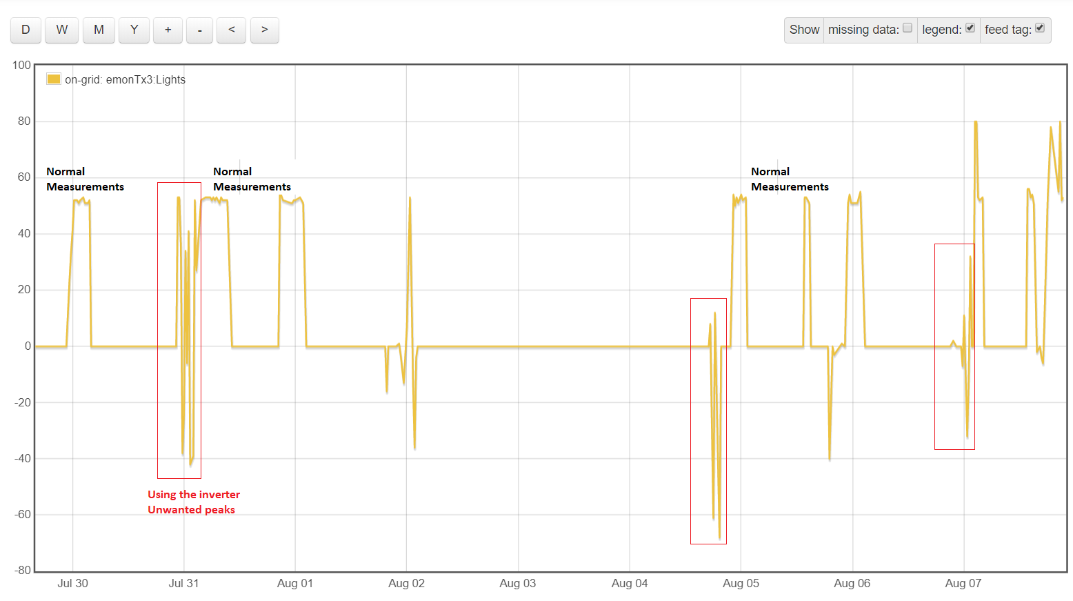
I am working on a system that measures the consumption of my office, but I have a problem with a specific measurement. This signal measures the consumption of light. In this case, my office has a photovoltaic system that sometimes feeds the lights and sometimes the lights are powered by the grid.
When the lights are fed by the grid, the measured signal is perfect. However, when the inverter of the PV system feeds the lights, the measurement shows peaks that correspond to the sensor measuring with another reference and parasitic currents (and in this case, the measurement should be zero).
This info is being sent to nodeRED and I have already filtered and treated the signal in this platform and it’s perfect!!! However, the real problem is that I must treat the signal from emonpi (or emon tx original signal) to generate correct and coherent feeds (kWh, wh accumulator, etc).
Can I implement a filter or code in any part of the emonTx (or in the base emonpi) to solve this problem?
Thank you very much guys. Sorry for the long message!
What you have labelled “Normal Measurements” is when the lights are being fed from the grid?
Do you want to know the power taken by the lights when fed from the inverter? Do you want that separate from the grid power?
Are you measuring the power in the right place? It looks to me as if the inverter is returning some power to the grid through the wire where you are measuring, and that is what you are seeing.
The easier place to implement a filter would be in the emonTx - provided that you know how you want to filter the output.
No. I need to have zero measurements when the lights are fed from the inverter.
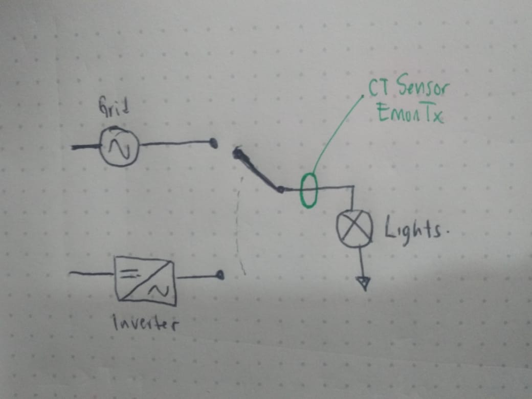
Yes, the place is ok. I’m measuring the light wire. ( I attach a quick scheme I made hahaha). What I’m looking is the noisy signal of the inverter, because it is not pure wave and because the adaptador of the emonTx has another reference signal.
I need not to see those signs (peaks) and that’s the reason why I need a filter.
That will mean that the power calculated might not be correct. The emonTx calculates the true rms power even if neither waveform is a true sine wave. If the voltage wave that the a.c. adapter measures is not the same one that works the lights, the power will be wrong.
I presume your filter is software.
If you look at the emonTx default sketch, the value of power comes out of emonLib and is copied into the data structure for transmission by radio.
If you have an a.c. adapter, that is in line 404 (for CT1): emontx.power1=ct1.realPower;
If you do not have the a.c. adapter, it is line 407 emontx.power1 = ct1.calcIrms(no_of_samples)*Vrms;
(And similarly lower down for the other CT inputs.)
You need to split that line and use the ct1.realPower or ct1.calcIrms(no_of_samples)*Vrms; part as the input to your software filter, and assign the output part to emontx.power1 so that it gets sent to emonCMS.
Why not move the CT to the grid supply (top left in the drawing)? Then it will measure the current to the lights when it is supplying and nothing when the PV is supplying.
Hello @djh !
Because I not only have that load but three other lines with different loads. However, I am measuring that wire too but with another clamp that I did not draw. Actually, that’s my measurement of total office consumption
The emonTx gets its voltage input from elsewhere. We know not where. What if the inverter isn’t synchronous with the grid? Even if it is, what if the voltage isn’t the same? I think we don’t know enough to be able to make any sensible suggestions.
The emonTx gets its voltage input from the grid (the same voltage of the lights when are fed from the grid), that’s why the “normal measurements” are so pretty, because the emonTx has the right reference and is measuring the power consumption of the lights.
When I switch to feed the lights with the inverter, there is a new current in that wire. The emonTx keep measuring but with a wrong reference signal because its adaptador is connected to the grid (the previous state) and the real supply comes from the inverter, so the measurements are incorrect and this signal are the peaks that I highlight in the image.
For me, this peaks and this noisy signal is not important to measure from emonTx (because I have another clamp in the correct place in this case (at output of the inverter)). That’s the reason why I want to filter this signal in the emonTx.
Thank you very much for your time and your answers ! C:
Pd. I followed the information that @Robert.Wall has given me in:
But I still do not understand why the a.c. adapter cannot be wired on the lights side of the switch? Is it because the other current inputs are not also switched to the inverter?
It’s because the office sometimes works on-grid and sometimes off grid. The adaptador is connected to the grid of the house, so the measurements goes well when is on grid mode. When I switch to the second position (Off-Grid), the load (just the lights) are fed by the inverter (that is off grid) but the adaptador is still connected to main grid. I can’t move the adaptor every time I switch to on-grid or off-grid.
And there is other thing… If I change the adapter at the output of the inverter, the other three signals of the emonTx that continue to measure the on-grid consumption of the office would be damaged.
Now I see what was happening. Your emonTx appears to have been working correctly all the time - but you were using it in a way that meant the data it was producing was not valid.