Hi everyone,
I am required to do a project where I have to create a detection system to detect the faults that could take place in a three phase induction motor like bearing faults, unbalance etc. using Motor Current Signature Analysis (MCSA). This system works by measuring the stator current and stepping it down using a current transformer/transducer, and then converting this analogue current signal to a digital signal through a data acquisition system (DAQ). This DAQ should be connected to a laptop with LabVIEW software where in LabVIEW I should detect specific harmonics in the stator current signal for each fault. So, now the problem I am facing is that I do not know which type of current transformer/transducer best to use for this project. And also in some articles I find them using three current transformers and three voltage transformers although I have known that MCSA can be implemented by sensing the stator current from only one phase of the motor. So, I do not know whether to sense the current from the three phases or only one and whether I need to step down the voltage too because I do not see why I need to do this although my work should be focused on the current. And if stepping down the voltage is required what type of voltage transformer/transducer should I use? So, please can anyone help? Thanks in advance.
Looking first at the question of monitoring one or three phases. It’s true that a fault on one phase will affect all three. However, you will get a much fuller picture of what is going on and you may well find it easier to detect and determine what the fault is and which winding or windings are affected if you have data for all three phases.
Consider next safety. Except for current shunts, the common current sensors - current transformer, Hall effect transducer and Rogowski coil - all isolate the motor circuit from your measurement apparatus by picking up the magnetic field surrounding the conductor. Unless your DAQ does so, you need to provide the same degree of isolation for the voltage measurements. Also, hopefully obviously, the voltages you present to the DAQ must not exceed the input rating. For our voltage measurements, and mainly because of EU regulations, we use readily available a.c. adapters. Even though it is possible to manufacture step-down transformers with negligible phase errors, the adapters we use have quite large phase errors, which might be a concern to you. I have heard good reports of small 1:1 current transformers used with a multiplier resistor (in the same way that a moving coil milliammeter can be used to measure voltage). We cannot easily do that because of cost to obtain regulatory approval, but you do not require that in a laboratory environment. I have not tested any of the voltage transducers for frequency response.
Because you have (I assume) full access to the motor under test, you can use a conventional ring-core current transformer, Hall effect transducer or Rogowski coil. I did test an earlier version of the c.t. that we use at frequencies up to 2.5 kHz, at which point the performance was starting to fall away (3% amplitude error and 10° phase shift). I have not tested the latest version, which in other respects has much improved performance. Hall effect devices and Rogowski coils go to much higher frequencies.
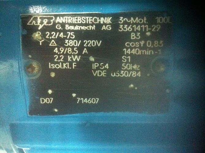
You don’t say the size of your motor, so I cannot guess what currents will be involved. But that will have a significant effect on your choice of device. You need to look at manufacturers’ websites and consider the performance (and cost) of the various options.
One more question which type of Hall effect current transducer do u think is better, closed loop or open loop?
That’s only a small motor, so well within the range of Hall effect i.c’s. (e.g. ACS712)
That’s for you to evaluate.
Hey I was working with something like similar project and if you still looking then this might help you to achieve over all aim
Hope this might help you
Hi…as per my observation you need to provide the same degree of isolation for the voltage measurements. Also, hopefully obviously, the voltages you present to the DAQ must not exceed the input rating. For our voltage measurements, and mainly because of EU regulations, we use readily available AC adapters. Even though it is possible to manufacture step-down transformers with negligible phase errors, the adapters we use have quite large phase errors.
I think, if you read the complete thread, I pointed that out in my very first response.
As for phase errors, those very much depend on the design of the transformer. If you look in the ‘Learn’ section here, you’ll find measured values for the a.c. adapter that we normally recommend.
@Nina Did you finish your project?
@Robert.Wall, I have got a similar project. In my project, I am using 2 three phase induction motors which are identical. During testing, I want to measure current in healthy motor and also from an unhealthy motor. But both are in good condition. So how can I make one with faults in coil and rotor bars? For eccentric fault, I can change the faulty bearings.
I think the easiest solution to that is beg or borrow a faulty motor. I’m not a motor designer, the last time I looked at the theory of induction motors was 50 years ago, since then I’ve done electronics applications and projects engineering, and any motors I’ve had any dealings with have been d.c.
