There’s a laundry list of potential errors in this project, but the big nut is getting the ADCs working properly in the appropriate range.
Ok. So it worth to divide the SPI MISO level with a resistor-based divider?
And why I get different results depending on how much CTs I poll?
I don’t have a definitive answer for that. The circuit is very flawed and the program has potential for that kind of error.
Two things pop to mind:
The capacitors to ground are .1uf and won’t help in charging the ADC at all. Without relatively big caps there, my circuits were always unstable.
You don’t seem to differentiate the offset value for the two current channels. The distinction between .1 and .4 amps is 5-6 adc counts, or about 7mv. Even with 1% resistors in the voltage dividers, you probably have that much variation in your bias voltage. So when you expose the program to one CT, it pulls the offset to its bias, and then visa versa.
But all that is arranging the proverbial deckchairs. The bias resistors need to be small and the grounding caps need to be large. Have you looked at your offset values?
dumbassprog, I second overeasy’s comment about the cap. It looks like your circuit comes from here:
https://learn.openenergymonitor.org/electricity-monitoring/ct-sensors/interface-with-arduino
You can read up there on the sizing of C1. By changing it from the recommended 10uF to 0.1uF you’ve changed its reactance from about 300 ohms to about 30 kilo ohms.
Changed CT circuit caps to 1uF with no luck. Maybe it’s worth to put 10uF tantalum or ceramic ones.
And it looks like I got a DC offset on current readings when two CTs are polled sequentially:

and for CT1 single:
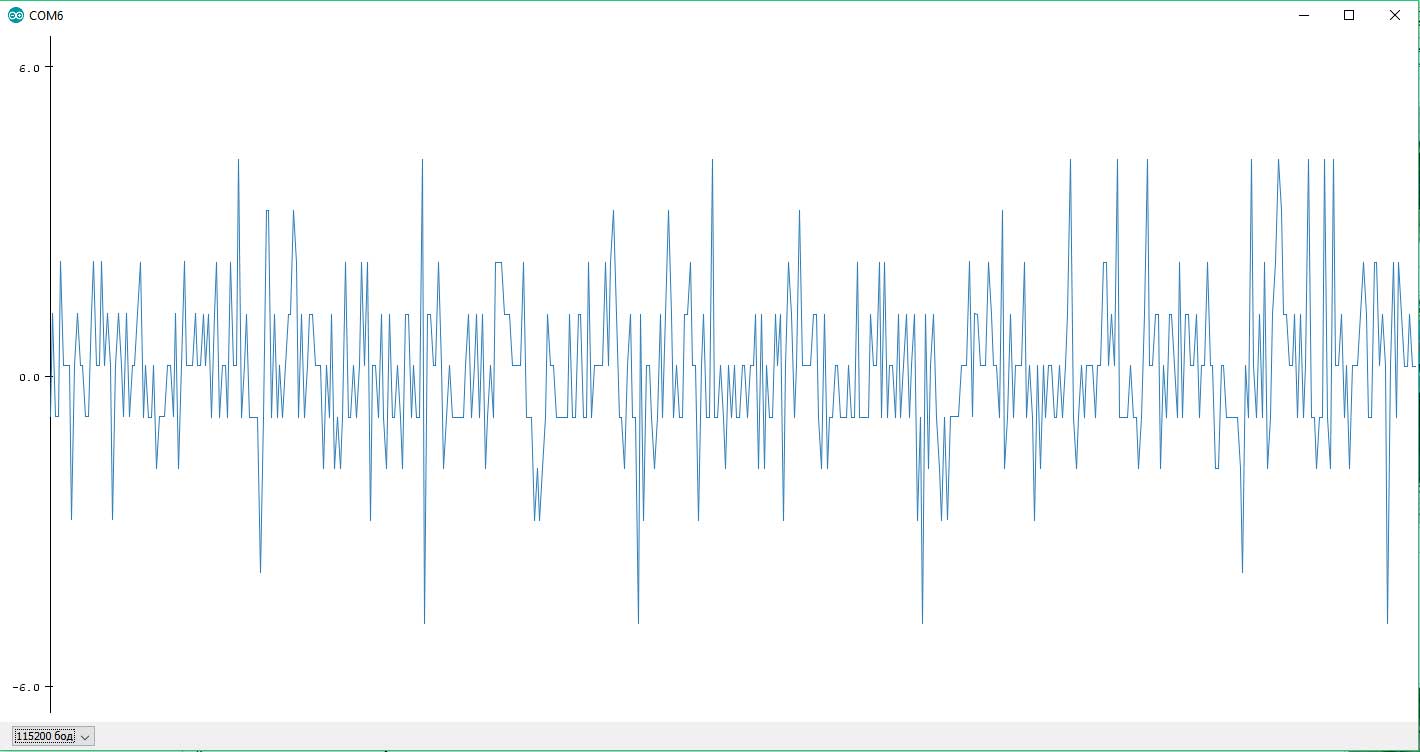
and CT2:

And now my calibration constants for now are:
#define ICAL 61.5
#define VCAL 255.8With 10uF tantalum capacitors on both CT subcircuits it became even worse: 0.47A at no load (was 0.4A)… So should I rebuild the voltage dividers with smaller resistors?
I don’t think I’d call it worse, i’d say it’s different.
I think the 12K resistors are close enough to the ballpark that they are not the big problem right now. The 470K on the VT definitely need to be replaced, but I think you may have done that because yesterday you stated that the cal is now in range.
This has the potential to make the readings change when multiple CTs are sampled. It should be relatively easy to keep the offset values on a per-channel basis. They are reflective of the bias voltage which can vary from channel to channel as each channel has it’s own set of voltage divider resistors. Have you measured the bias voltages on each channel with a voltmeter?
You mean that it wold be better to use more precise resistors than standard “stock” 5%?
Between these two points

for CT1 I have 0.779V and for CT2 I have 0.795V
No, i don’t mean that at all. You can use 5% resistors if that’s what you have. What I’m saying is that regardless of how accurate your resistors are, the bias voltage will probably be different for each CT channel.
The code you use to “correct” the offset value takes many samples to move the value significantly and doesn’t really settle down to a specific value but rather creates a low amplitude wave that is out of phase with the signal you are measuring. It doesn’t bode well for accuracy. You would do better to determine the ADC value with no input for each channel and fix the offset to that.
In any event, the point is that the offset is a per-channel attribute and you’re maintaining it as a single value.
If I understood you correctly I need to detect virtual zero level (2.5V i.e. 2048 in ideal case) and use it as the starting point of voltage/current values accumulation?
No, the mid-point is a per-channel attribute. You already differentiate the voltage channel offset, now you need to define the current offset as an array:
then search and replace all instances of offsetI with offseti[currentCh];
1 Like
Wow.
Looks like you saved me)) Need some more tests but now I have 0.07A at idle and 720.13W with boiler connected while my meter shows me the same number: 0.720KW. ALso tried to wrap the phase wire 3 times around the CT clip and got 2142.13W (230.89V voltage and 9.28A current, so 2142.13 / 3 turns = 714.03W which is almost there). Next I will try the larger loads and maybe will make some kind of error correction table (still don’t know whether this is a good idea or not…).
Thank you SO MUCH for your help!
Great. You’re in the ballpark and can take it from here. Here are a few things you should ponder when you get a chance:
Your zero crossing algorithm could be more accurate. Look for a change in sign of the filteredV by using Xor on the sign bit.
Check your samples per cycle. If you are using an ESP8266, you shgould be getting hundreds of samples per cycle (thousands for 25 cycles). If you tighten up your zero crossing you can get good just as good results sampling fewer cycles. I sample one cycle, with over 600 samples at 60Hz.
Try to cut down on the double precision floating point arithmetic in the loop. Most of those values can be maintained with long integers. Use floating point to compute the results after sampling is done.
The phase calculation you are using with a factor of 1 does nothing. If you can get hundreds of samples per cycle you can do phase correction by simply skewing the sample pairs. In any event, the phase difference between your VT and an SCT013-000 is probably less than 1 degree anyway.
Good luck. I’m not going to work these issues with you. That’s the fun and you will learn more working through them yourself.
One last thing. This is most probably sag from the high impedance input. Using 4.7K bias voltage resistors should improve that.
Because you changed from a class instance in C++ to a function in C, hence the filter is seeing the step change due to the different bias offsets added to each sample. So in effect, it’s adding a wave at sampling frequency to each input.
1 Like