I decided to use the Christmas break to try and extend a CT to my outside meter cupboard so that I can directly measure all power before the Henley block which was put in a couple of years ago when we had a Tepeo ZEB installed.
So far, I have taken an existing CT, cut it and joined a new cable with a new jack plug on one end and wagos joining the 2 cables.
Strangely, if I plug it into the emonTX, I get a positive value which is out by a few hundred Ws, but if I plug it into the emonPi, I get a negative value.
I might just have confused myself, so thought it was worth checking if I was missing anything when doing this with the older hardware?
I wouldn’t have expected the version of the emon hardware to have any significant impact.
I’ve extended CT cables for some other types of hardware recently and one of those specifically said not to use ‘spring contact connectors’ like Wagos - and someone who’d tried those reported having issues which went away when they switched to a ‘better’ connection. I’d advise a soldered joint instead, or possibly a screw terminal (‘chocolate block’) connector.
Could you also confirm how long an extension you added, and specifically what type of cable you used for the extension? Longer extensions often need surprisingly high-spec cables.
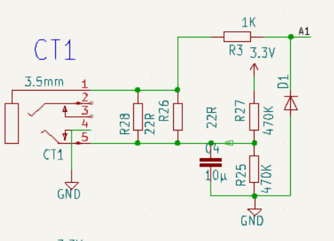
(This is essentially the same as the diagram in Docs, which is wrong for the emonPi2 & emonTx4 and subsequent versions.
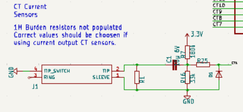
You can see the a.c. ground actually floats at 1.65 V d.c. above true GND, and is the plug TIP. The signal is on the plug sleeve. I would advise a twin core screened microphone cable, with the screen connected only at the Pi end to true GND, the two cores to the tip and sleeve of the plug, and to the cores of the c.t. cable ignoring the screen. Try to keep the polarity of the cable cores as they were, however if it reads with the wrong sign, either reverse the c.t. on its cable or add a ×(-1) in emonHub OR in emonCMS.
I would solder every time unless it is completely impractical.
Oh yes it does. I never understood why this configuration had been adopted, @rupert provided an explanation for why it is particularly bad in the presence of noise from a SMPS in a PM to Trystan, which as far as I know has never been published.
Following that, everything since the emonPi V1 and emonTx3 has the “earthy” side of the input connected to GND, not floating at 1.65 V d.c. above GND.
@Robert.Wall - can I check, when I’m connecting the plug at the emonPi end, does the screen from the cable connect to the plug, or does it need to connect to another earth?
I can’t spot anything in the Amazon listing for that cable about the cores being twisted together. If they actually are, that’s fine. If not, you might have more success with twisted-pair cable.
It appears to be a round cable, I think I can see the filler in one of the images and the cable is said to be flexible, so I think it is very, very unlikely that the cores are not twisted.
I think the soldering and screw terminals may have been the bit that made the difference. I took me a few goes as I was getting very confused by trying to compare output from a ‘new’ emonTXv3 to the emonPi between the new and old cables.
For some reason, switching a cable between the emonPi and emonTX changes the reading from positive to negative…
I now seem to be getting values within 50 - 100w of each other, and I’m going to call that good enough
Just add a little,.. I had the same issue,.. I could monitor within my consumer unit,.. but needed some ‘extra long’ cables to be able to monitor within the DNO box,.. in order to monitor different property supply’s, eg house, garage, car.
It maybe a premium microphone cable,.. but it does the job of current cable extension very nicely.
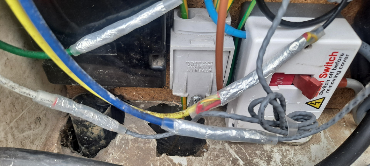
It did take a while to make of connections,.. but as noted above I did earth/screen the cable at the TX4 end., then at the other new end I used the screen as a connection to some foil, but not electrically connected, ( salvaged from some other screened cable ),.. to screen the soldered connections, which were insulated with heat shrink, to try and ensure a ‘good screen’,.. and clean signal.
have attached picture of my final efforts,.. I used some clear glued heat-shrink,.. which ( hopefully ) made for a better IP rating within the joint.