Can I use an extension cable with the current sensor jack that comes with the EmonPI? I need about another 0.5 to 1m to comfortably fit the unit as it comes through the wall from the external electricity meter? If so any recommendations on where they can be purchased at a reasonable cost and will not cause any potential problems with the readings?
I have used standard 3.5mm M-F extension leads of various lengths (either stereo or mono) without any problems. These can easily be bought online or from any audio store. Some tape around the joint to deter dust from entering may be a helpful.
When a CT lead needs to be extended, my preference is to cut the original lead in two and solder in a new section with plenty of heat-shrink tubing around each joiunt. That way, the original connections at each end don’t need to be disturbed.
The current sensor is a low impedance interface (it’s working into <100 ohms) so is not particularly sensitive to interference. Measuring real power when an AC voltage source is available will always give better results than when measuring AC current alone.
Hi Glyn,
I suppose that an extended cable will be always be susceptible to picking up some extra noise. The real point is, does it matter? When monitoring real power in conjunction with an AC voltage source, I have never noticed any degradation because of extending the CT’s cable. For other types of measurement such as Irms, additional noise may have more effect.
PS. Could somone please port my picture from the old forum onto this one? I can’t see how to do it and don’t like just being “C”. At least its the right letter!
Thanks
calypso_rae
Done! - however the image was reduced for the old forum and the 50x50 image doesn’t scale well for the bigger profile picture here on the new forum, do you have the original?
I think it very much depends on the nature of the noise you’re picking up. If it’s white noise then yes, multiplying it by a 50Hz sinewave will certainly nuke it. But if you’re picking up noise with a 50Hz component then it will show up.
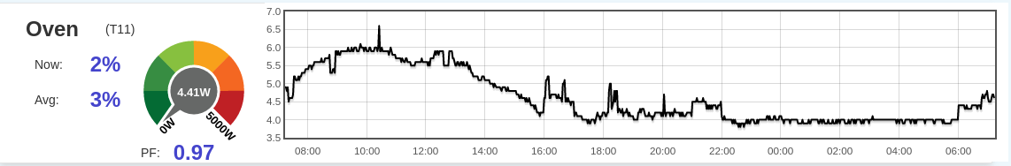
I’ve got 18 CTs each with 2m of unshielded twisted pair cable all jammed down the one conduit and I definitely see a small amount of crosstalk between them. You can see it most clearly when looking at a very low-power circuit like the Oven just sitting being a digital clock:
When the house is quiet from 22:00 to 06:00 you can see it reports a very steady 4W, but all those other bumps are bogus and I can pretty much identify them all as crosstalk from other circuits. The big slow hump from 08:00 to 16:00 tracks the PV output well. The jumps at 16:00, 21:00 and 06:00 are the pool pump coming on. The stuff just after 18:00 is the hotplates and the spike at 20:00 is the electric kettle.
I don’t know how much of this is pick-up in the 2m leads Vs pick-up by the CT being too close to neighbouring circuit conductors. Also my set-up is very different from yours: my CTs have an inbuilt burden so my cables are carrying a voltage signal rather than a current signal. And at 333mV rms at full-scale it’s an extremely small voltage signal. That bogus 2W when the PV is at its peak represents about 133uV rms of pick-up.
But the underlying principle is the same: you can only rely on the times-V calculation to filter out white noise and in these environments the noise typically has a very clear 50Hz sine wave running through it.
On the subject of CT leads, the extensions should not be grounded at the receiving end but should be grounded at the CT end. I’ve always advocated that, and nobody appears to have complained yet about excess noise. In any case, the CT is a current source loaded with a very low impedance, so a fair current needs to be induced to get a sensible voltage, and that’s hard if a proper screened twisted pair cable is used (because the magnetic field in adjacent loops of the twist will hopefully be more-or-less uniform and will cancel, and the earthed screen will take care of electric fields). I must write it down for BB on fine day. ToDo++.
I hate to bring back old threads, but I think for this it is applicable. EmonPi rocks!
I have one that I purchased from the store, and I have been using it for a few years now. I need to extend the cable. This is what I have with the clip on CT’s purchased from the store: emonPi Energy Monitor - Shop | OpenEnergyMonitor
I need to extend them about 1 to two meters. Isn’t the ground in the cable? So this right:
I was also thinking about running some conduit for each CT, but that is overkill…
My recommendation is that you read the article in the Learn section.
That lead might not be suitable because the plug sleeve, which is likely to be connected to the cable screen if it is a screened cable (it doesn’t say, so maybe not as it’s for headphones and speakers) is actually the signal conductor, whereas the plug tip is the ‘earthy’ side of the connection.
A length of 2 m won’t be disastrous, but it’s better to do it correctly and avoid problems.
Some EE terms I am not used to, but it got the point across. I am just an IT guy, and while I have built some custom cables before, and love to:
Can I just get some unscreened headphone extension cables, and run each through some conduit? The conduit will be grounded, so that should remove any interference concerns?
If it’s only 2 m, and there are no local sources of interference, e.g. cables feeding fluorescent lamps with glow-tube starters or induction motors, then it’s probably OK to not bother with earthed conduit. But if you’re worried and it’s easier to do first time round than as a retro-fit, then go for it.
I have a wall ripped open, and I just ran a new service to the building. I am installing the emonpi in a better place. For about 5 mins of time, I can run 2x 1/4 inch flex conduit and put a headphone cable in each.
I just wondered if that would solve all the problems. I have no time purchasing good screened cable, and doing it like it says in the learn section. But I was just wondering what is the point, if conduit will do the same thing.
The service wires do run close to where the wires where the CTs will be, and for all I know I could put something that would cause interference in the future. I want to install, an never deal w/ again.
Is it safe to say that the conduit, and screen on the cable do the same thing?
In that case, I’d install the conduit and some spares, on the grounds that it’s easy and cheap (in time and effort, if not money) to do it now.
They should be roughly equivalent. Earthing it will provide screening against electric fields, and if it’s steel conduit, it should help against magnetic fields.
What is OK is cables crossing. What is not OK is cables running parallel and close for any distance. By any measure, interference is something of a black art, sometimes it cooperates and obeys the rules, and sometimes it plays havoc from the most unlikely sources.