I’m on iteration #695 of my compact jack shield, and thought I’d share it with you guys in case it helps any future OEM people get up to speed in the future.
I put a YouTube video that shows a bunch of the designs that led up to this.
")
In case that video is ever removed, here are some OEM-hosted images/descriptions of the current one. It’s super simple, and about as compact as you can get:
The basics:
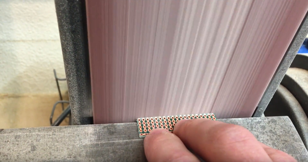
- Modify a breadboard-like perf board
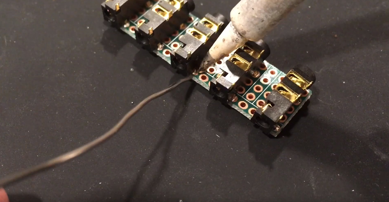
- Solder on some jacks
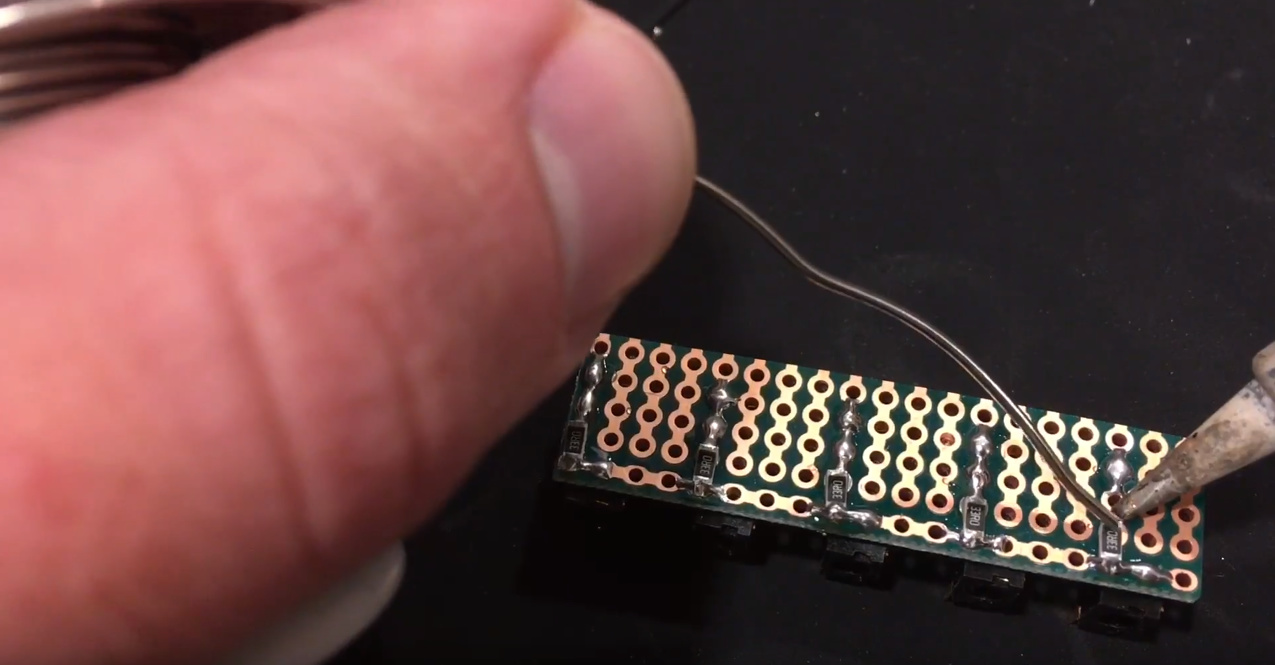
- Solder a burden resistor on the back
Suddenly this sounds way too simple and obvious. Watch the video for more details, but you are smart people so I’ll leave you with some basics below.
.
Modify the boards:
.
Put some jacks on the side without the traces
.
Add SMD 1206 burden resistors to the back, starting with the solder that’s already on the shared rail:
.
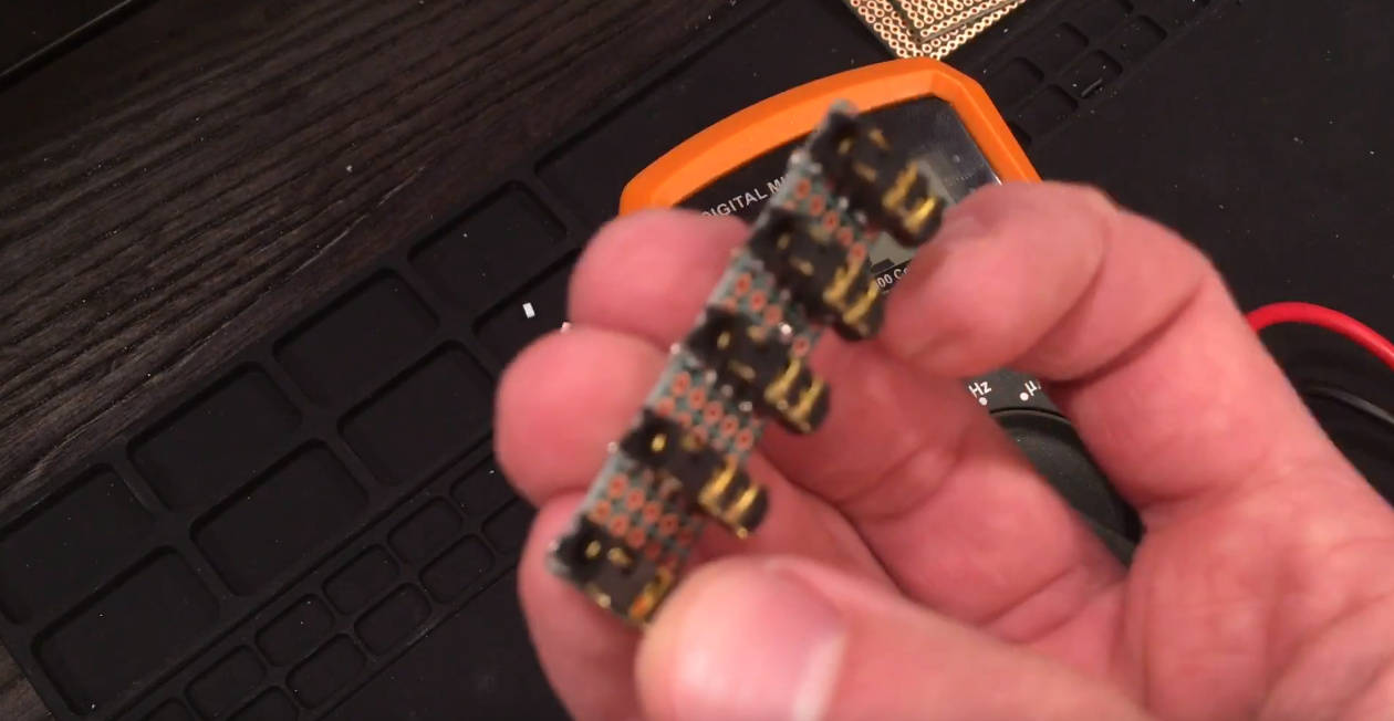
Enjoy the compactness:
.
Own your problems and research as necessary:

.
What you end up with: a series of jacks w/ burden resistors that’s as close to each other as the 3.5mm PLUGS will allow. It’s dirt cheap to make this, easy to make, and easy to wire.