Unless it’s some bespoke EV I’d say it’s most likely true. On the DC side they’re capable of charging way faster than the ~7kW provided by the on-board AC charger - anywhere from 70kW to 350kW depending on the car. Of the 3 I’ve tested (Tesla3, MG-ZS and EQC) they all appear to draw the EVSE’s specified max current (typically 32A) continuously, regardless of what V does. As V goes up, the car reports 7.6kW charge rate, as V goes down it reports 7.0kW etc.
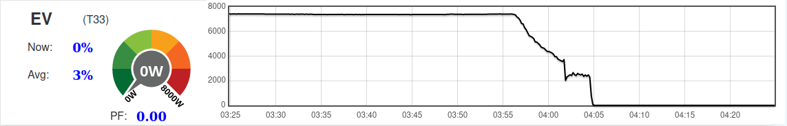
The only exception to that is on the rare occasions I charge it all the way to 100% because of an imminent roadtrip the next morning. In that case you do see some tapering on the AC side towards the end of the charge:
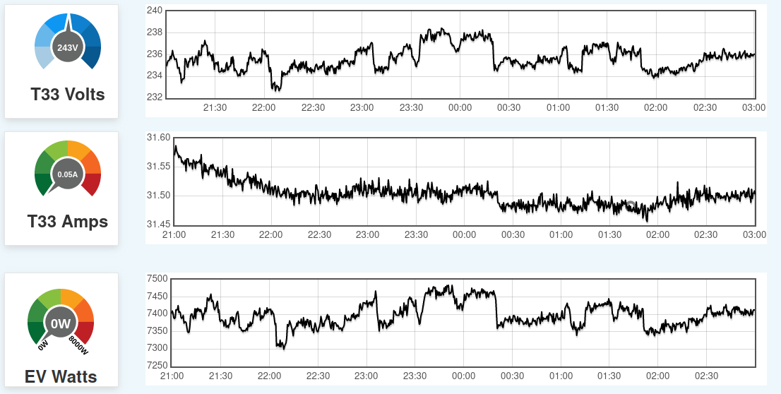
Yep, see also the plots in post 7 above, where I plot V and I together. When I get a chance, I’ll knock up a time-aligned zoomed in plot of all 3 (V, I and P).
I have no way of monitoring the voltage on both sides for a period of time sadly.
We have a Skoda Enyaq 60 with 50kW DC charging, I k ow from the Skoda app when plugged in at the house it says its only pulling 6.5kW from the homes charger.
That’s quite low, assuming your EVSE is wired/configured for 32A I’d expect it to be in the low 7s. What’s the current rating on the EVSE circuit breaker? And what’s the make/model of your EVSE? The most common step below 32A is 20A and you’re definitely pulling more than that, so I’m guessing it’s set up for 32A. That makes me think your voltage is very low, at least while charging.
Its a 7kW pod point, the Fuse Saver clamp was installed on the Primary side 25mm Tails im wondering if the voltage difference between that and what the Pod Point is seeing was the reason for the 500w “loss” i will test it when my partner returns with the car.
The unit is suppled from my main DB via a 40A MCB in 10mm Twin & Earth cable to a separate “EVDB” with a double pole Type A 40A RCBO feeding the Pod in 6mm 3 Core EV Ultra SWA cable.
On the Setup → Inputs page of emonCMS, look for the emonpi section, and a line for Vrms. At the r.h. end, click the spanner, and if you don’t get offered it as the first choice under “Add process”, select “Log to feed” in the first drop-down. All the other options should be OK so click “new” to create it, then save and close the page. After a few minutes to gather some data, you should be able to go to Graphs, click “emonpi” and you should be able to select Vrms and see a graph - you can choose a time scale to suit, the ‘Y’ axis is scaled automatically but you can change it at the bottom, below the graph. There’s more about all this in the Guide.
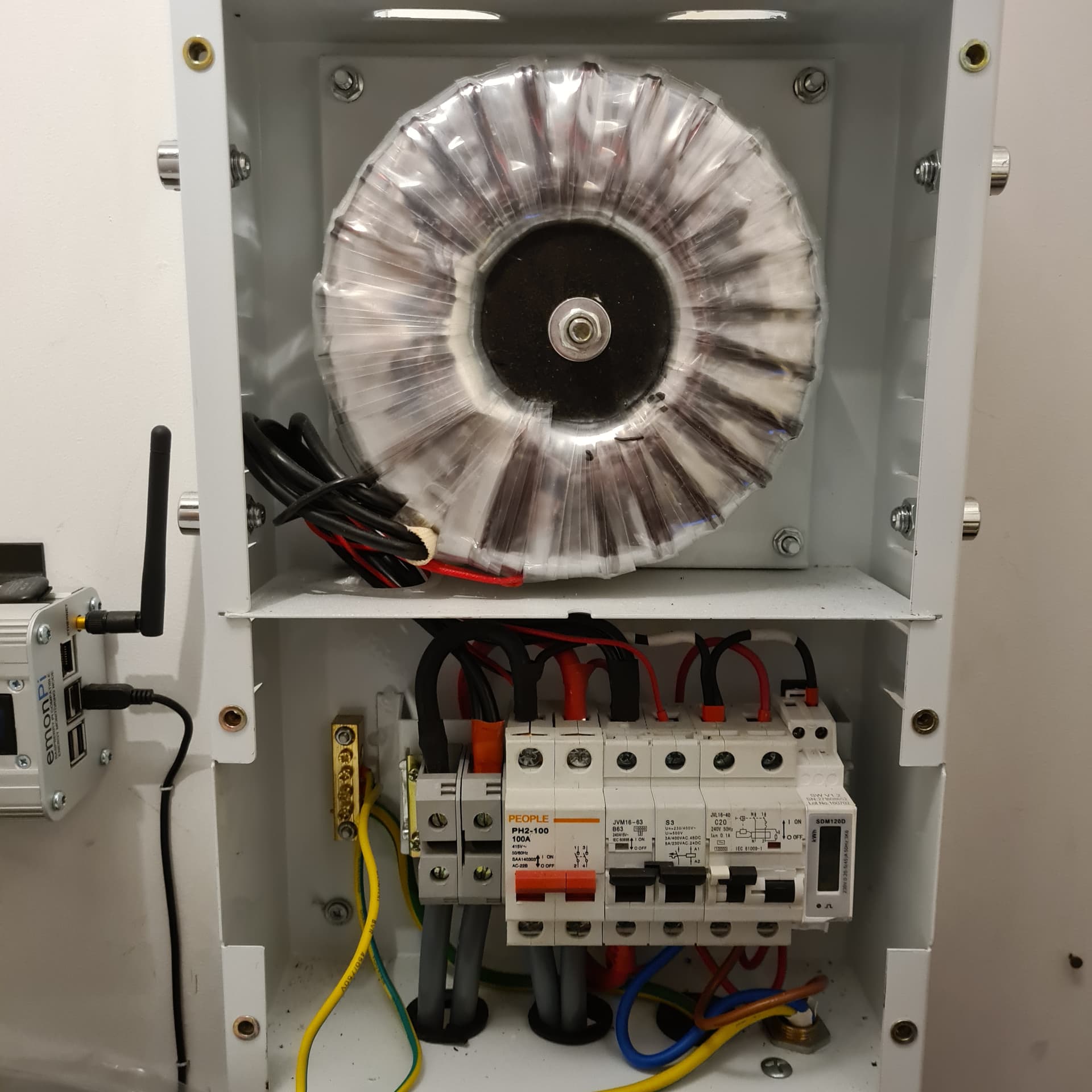
I’ll look at that when I’ve worked out how the internals of the VoltDr are wired.
Yes, quite possibly. Is that the device that measured the 6.5kW? Anything that gets it voltage from one side of the transformer and its current from the other is going to be out. Does the car itself report how fast it’s charging? Unfortunately, that is often a different measurement again, it’s likely to be the DC power going into the battery so can be quite a bit less than what your AC meter reports. The AC meter will include any losses/cooling in the on-board charger. But if the car reports that it’s getting more than 6.5kW then we know the 6.5kW measurement is bogus - probably for the reason you suggest.
The 6.5kW reading is from the Skoda App so presuming that’s the reading being obtained by the onboard BMS/Inverter nothing to do with anything withing my home set up.
Yep, and it’s probably the DC power into the battery. It’ll no doubt vary a bit from car to car (and climate if it needs to heat the battery) but by way of comparison, on mine at 239.1V I see 7550.5W on the AC meter, and the car reports the charging rate as 7.3kW (presumably DC).
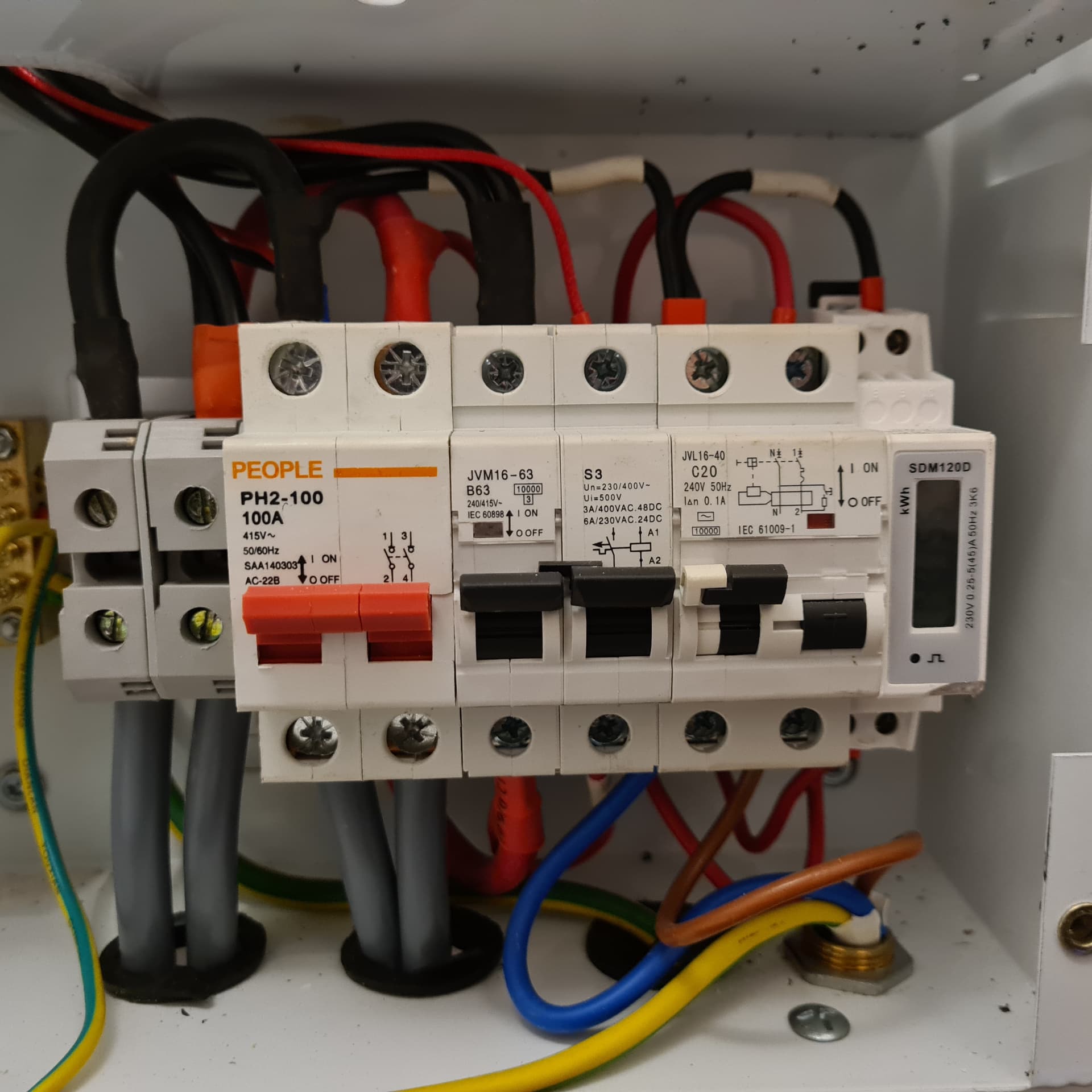
So, rather as I expected, it appears that the Inverter and PV infeed is on the mains (incoming) side of the auto-transformer
If you put CT1 on the cable from the auto-transformer to the consumer unit, and move CT2 inside onto the brown wire to/from the inverter, you’ll have a “standard” Type 2 installation except that you’ll need to multiply the PV power/energy by 1.081 to account for the higher voltage it’s working at.
(If you save a feed that’s export-only energy, you can calibrate this over time by direct reference to the SD120)
You’ll then be reading the house + EV charger directly on Power1, and the PV import/export directly (after scaling/calibration) on Power2.
Assuming you follow our convention that power used and power imported are both positive, the nett grid power is then Power1 + the scaled Power2 (don’t use “power1pluspower2” - that sum is done inside the analogue front end, it’s the wrong power2 for you).
I think this should be more accurate as you are less likely to be subtracting nearly equal numbers from one another.
I understand the positioning of the CTs and what you are asking in terms of the modifications to the inputs, i am just not 100% sure how to implement these within the EmonPi inputs area and what modifications i need to make to the current set up i have ?
Would this be correct ? Also you say do not use power1pluspower2 should i delete this input ?
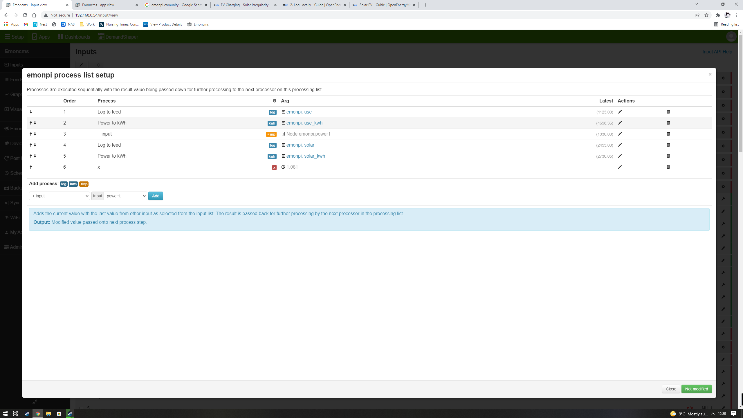
I don’t know which Input that process list is for, but it looks wrong to me.
I wrote above:
What that means is, you don’t need any “special” processing on Input1
Input 1:

Log to feed        use
Power to kWh       use_kWh
but on Input2 you must introduce the multiplication:
Input 2:

× 1.081
Log to feed        solar
Power to kWh       solar_kWh
+ Feed             use
Log to feed        Grid
Power to kWh       Grid kWh
Allow positive
Power to kWh       import_kWh
use and use_kWh then give you the house + EV charger power & energy respectively, solar and solar_kWh the same for the P.V., Grid and Grid_kWh the same for the nett Grid values, and finally import_kWh is just the import component of Grid_kWh (which will go negative if you’re a nett exporter of energy).
The names of the Feeds correspond with the names/descriptions in MySolar.
I think that should work.
You can’t (or rather; if you do, it will promptly reappear). Just ignore it, don’t use it.