We took delivery of an Enyaq last week and stuck it on charge yesterday at home for the first time with our PodPoint charger.
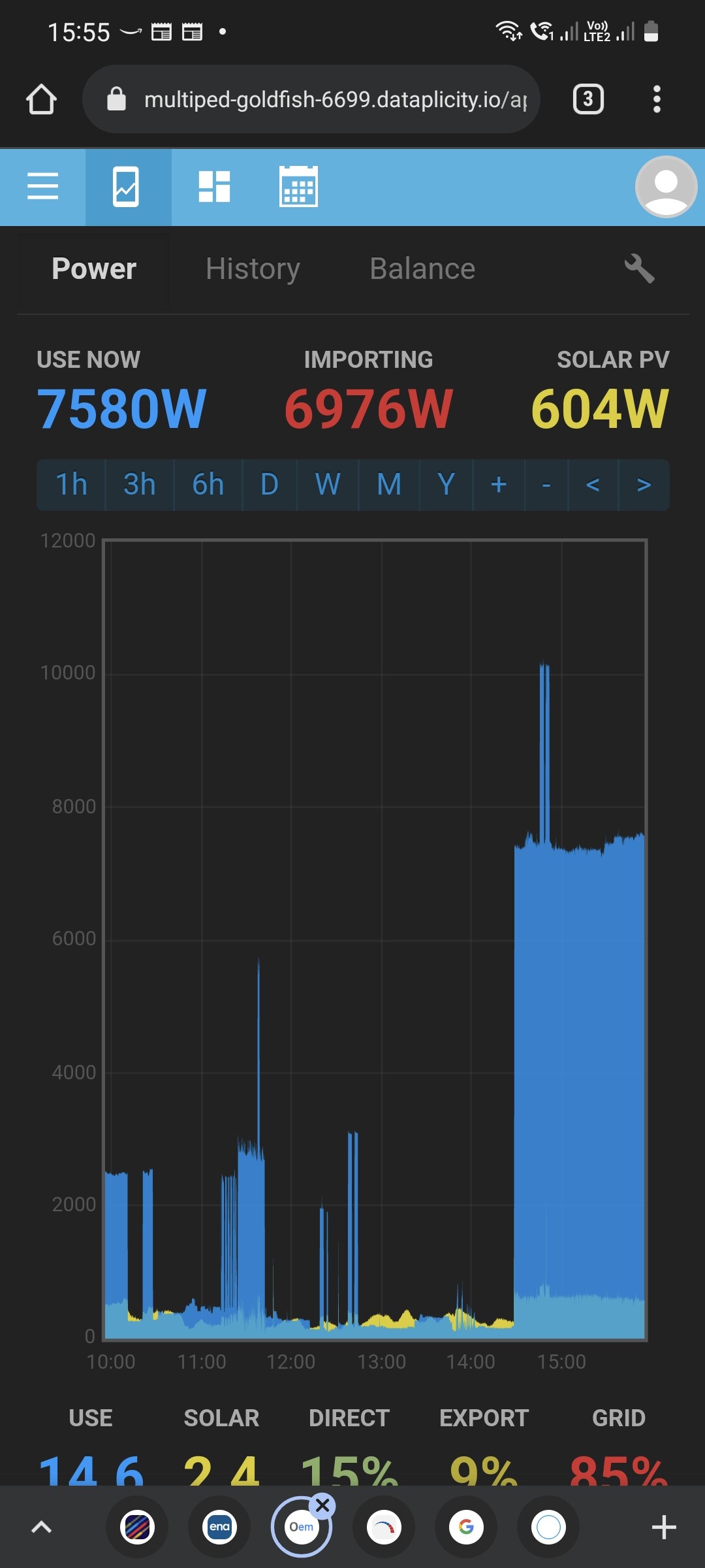
I opened up Solar dashboard to have a look at the current draw and noticed that we had “460W” of Solar being produced in pitch black. Obviously this is an error within the system but can anyone explain this and possibly a way to rectify it at all ?
Hello @BioHzrd can you provide a bit more information on your monitoring setup? Is this an emonTx or emonPi? how many CT’s and what circuits are they connected too? Are you using an ACAC adapter for voltage sensing? I assume all single-phase?
It’s is an EmonPi set up with two CT clamps, I am using the provided adaptors to to ascertain voltage readings. The CT clamps are located on the homes tails to read Solar Input & Home Draw.
That’s a little ambiguous. Can you clarify “on the homes tails” - do you mean the meter tails between the supplier’s fuse and the meter, or between the meter and any Henley blocks or the consumer unit? Where does the PV infeed from the inverter connect into the system? Maybe a single line diagram or a photo will help.
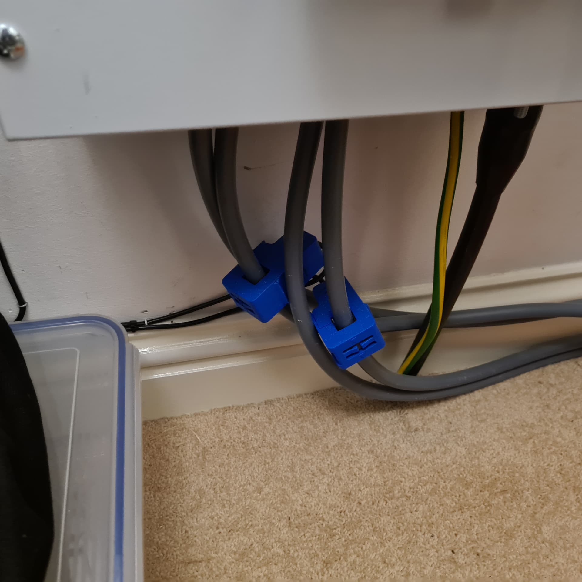
Clarification…the clamps are positioned on the 25mm tails on the consumer side of the home electricity meter and one on the live tail exiting the solar voltage regulator that then interiors I to the home consumer unit.
OK, that’s clear now. In the top picture, the right-hand c.t. is on the incoming grid supply, the left-hand is on the feed to the house and downstream of the Growatt “Optimiser” and the PV infeed.
That doesn’t appear to be what you first wrote.
The immediate problem is a “feature” of the Growatt - “Output voltage range: 0.925*Vin (approximately input voltage less 18V)” which means that it has automatically introduced an error of around 7.5% because the two places you are measuring current are not seeing the same voltage.
With the c.t’s as they are, you have neither a ‘Type 1’ nor a ‘Type 2’ set-up, so you’ll need to derive the PV contribution from the quantities you are measuring - having allowed for the 7½% discrepancy the Growatt has introduced.
I think you need to look at the processing you’re doing to derive the values you’re seeing. I don’t think the EV has created the problem, it might have made it bigger so that you’ve noticed it.
Incidentally, the advertising claim “to reduce power consumption of electrical appliances and save on electricity bills.” is not universally true. Some types of load obey a “constant power” law (e.g. computer power supplies) and these will automatically increase the current to compensate for the reduced voltage. Some motors may run at reduced efficiency and actually increase the power consumed because of the lower voltage, while heating loads (kettles) will just take longer to reach the required temperature and while the power is reduced, the energy used will be the same.
It sits there sucking 31.5A almost oblivious to what V is doing. Like your heating load example, a lower V just means it takes longer to charge, but in this case Power is proportional to V rather than V2.
As tungsten lamp efficacy ∝ V² (nearly), it isn’t hard to envisage the situation where SWMBO decides it’s too dark and turns a second lamp on as well, so rather than saving 15%, the power increases by 70%.
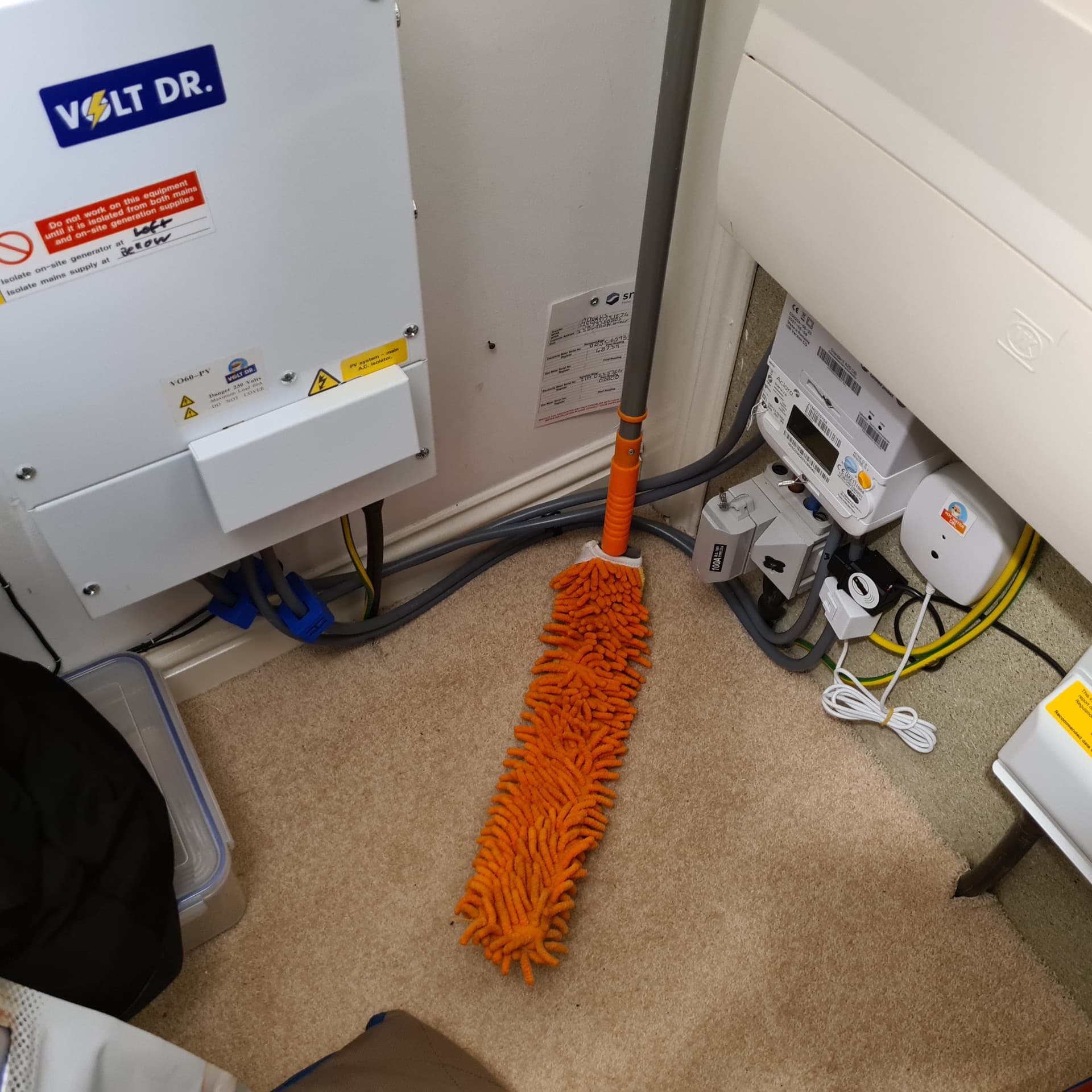
I would check to see if there’s a good reason for it being there. Looking at the data sheet, it also contains a (your only?) generation meter, so I think if it’s the only one (your supplier hasn’t provided one), you need to replace that, plus you’ll need the appropriate isolator, Henley blocks, protection, etc.
I suggest you log the voltage downstream of the regulator and check the range of voltages you’re seeing - first making sure your voltage measurement is accurately calibrated. Bear in mind that even though the UK voltage is a nominal 230 V -6% +10%, that (as far as I know) is a fudge and the ‘centre’ voltage remains at 240 V.
If you’re regularly going over 235 V ( = 254 V × 0.925) then I’d retain it, because your supply is out of tolerance on the high side.
If you’re regularly going below 216 V (= 230 V - 6%), then I’d definitely remove it, because its output is out of tolerance on the low side.
Otherwise, what does it cost to run (there must be some losses - it’s got ventilation slots to let the heat out) and is it worth the cost of removing it?
Alternatively, if you know what you’re doing, what I suspect is in there apart from the stuff you’d need to replace, is an auto-transformer, which would be easy enough to take out of circuit. That way, you’d keep the box and replace the auto-transformer by a suitable wire link.)
My personal view is the previous owner of your house was taken in by the advertising and most likely hadn’t evaluated its veracity under all circumstances.
You’re really interested in the output side voltage, which you can check anywhere in the house. We know the input side voltage is 1.081 times that. If your emonCMS is not logging the voltage, do start logging it now (ideally, check the calibration first, you can tweak the voltage reported and logged by adding a calibration on the Inputs page).
The question still remains - what does your voltage look like over time? If it’s consistently 238 on the output, I’d suggest you should probably leave the auto-transformer in circuit. But if it never goes above but goes below 220, then I’d take it out.
I hope you don’t mind me calling your current transformers c.t’s - that’s how I’ve known them for the last 50+ years, “clamps” to me are things you use for woodworking.
You’ve no option but to leave your c.t’s where they are, but you need to fiddle the maths on the Inputs page of emonCMS to get the correct values.
The one on the C.U. tail is “correct” in that it’s measuring the current to the House and using the correct voltage with it to calculate the power/energy.
The other one on the Grid side will be reading the power low, because while the current it is reading is correct, it’s lower than the current would be on the consumer side of the auto-transformer because of the transformation ratio of the transformer. And it’s using the voltage on to consumer side to measure the power. So that power should be multiplied by 1/0.925 (according to the data) or 248.2 / 238 according to your measurement.
Explanation: the auto-transformer lowers the voltage on the house side by a factor of 0.925, therefore the current on the house side increases by 1/0.925
Or if you prefer, looking backwards through the auto-transformer, the voltage is stepped up, therefore the current must be stepped down.
This is because, barring losses, the power on each side of the transformer is the same.
What you are reading then is house power/energy (correctly), and grid power (incorrectly, but it can be put right with a fiddle factor).
Our convention is grid import and PV are both positive:
PV generated = House Power - ( Grid power × 1.08) (or 1.043 - their figure or yours)
You can do the multiplication on the Inputs page in emonCMS for the Grid Input with the calibration process, then log Grid power to a Feed; then for the House Input you log that to a Feed for the House Power, then subtract the Grid Feed and log the result to the PV Power Feed.
The fly I can see in that ointment is you’re subtracting two nearly equal quantities to arrive at the PV power, so very accurate calibration will be needed. That’s probably best done with minor tweaks to the “1.08” constant in emonCMS to get that to agree long-term with your Grid meter, then add another calibration value to the house c.t. so that the PV infeed power comes close to zero (but ideally a tiny negative value) in the dark - because the inverter will actually be consuming a few watts then.
Isn’t that transformer likely to introduce quite a phase error? It seems you’d want your VT and all your CTs on one side of it, or the other.
If you could find a way to move the grid CT over to the PV feed you’d achieve that. But you’d need to find a way to split the inverter’s Active and Neutral out, perhaps inside the bottom of the Volt Dr.? Then you could just subtract one CT from the other to know how much the grid is supplying (or being fed).
An auto-transformer with a ratio of 0.925? I didn’t think it would be very much at all, and now having done Fourier on my Variac, I’m afraid your fears were unfounded.
Over a range of 16 V above the input voltage (around 236 V at the time) to 40 V below, I see the phase shift vary over the range +0.01° to +0.03° . I think we can disregard that. It is within ±0.06° all the way down to 50 V out, it’s only below that the phase shift leaps up, to +0.32° at 15 V out.
That would be the best idea. We don’t (yet) know just how the PV is connected in relation to the Volt Dr, I can’t see it being anywhere other than on the primary side - but that’s only from thinking about losses.
That looks very promising then, for your suggested scaling solution.
Good point. Another argument for it being on the primary side: most jurisdictions place requirements on inverter behaviour as the voltage approaches limits. To that end, you’d hope the inverter is monitoring actual grid voltage rather than stepped down grid voltage.
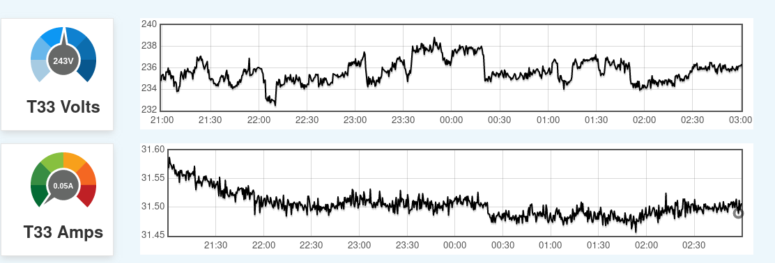
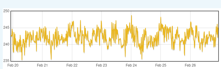
As you say above, a long term (at least a week) log of calibrated voltage readings is needed to decide if the transformer is doing anything helpful. If that does show the grid is running high, how easy is it over there to get them to come out and adjust the local transformer tap? They’ve retrofitted remote voltage and current monitoring on the final distribution transformers around these parts. Here’s what mine looks like over a week (as measured by me, not them):
It’s possible, I’ve never needed to do it, but people here have reported that they take some convincing before they’ll even put a monitor on.
Yes, it looks as if that won’t be forthcoming, yet it would be exceedingly helpful in deciding whether to keep the Volt Dr or not.
Not knowing how the on-board charger controls the charge rate, is that necessarily true? If it’s controlling the d.c. current into the battery (which will be constant power for any given battery voltage), then surely it will be constant power on the a.c. side too, so 8% more current to compensate for the 7.5% lower voltage. And 8% more IR loss on the cables feeding the car, thus a negative saving on the electricity bill.
If it’s regulating on a.c. current, then yes, 8% longer, so no saving on the bill. I guess whoever wrote that hadn’t heard of Q = I × t.