I am trying to use ESP32 and current sensor SCT-013-020 to post Current data (Irms) to ThingSpeak.
To problem is the following:
When i run the sample program for reading Current data it works fine:
#include "EmonLib.h"                   // Include Emon Library
EnergyMonitor emon1;                   // Create an instance

#include <WiFi.h>
const char* ssid = "********";   // your network SSID (name)
const char* password = "**********";   // your network password

void setup()
{
  Serial.begin(9600);

  emon1.current(34, 9);             // Current: input pin=34, calibration.

}

void loop()
{
  double Irms = emon1.calcIrms(1480);  // Calculate Irms only

  Serial.print("Power= ");
  Serial.print(Irms*230.0);	       // Apparent power
  Serial.print(" ");
  Serial.print("Irms= ");
  Serial.println(Irms);		       // Irms= Root mean square current
}
But, when i connect to my wifi network to be able to send data to ThingSpeak the sensor gives me wrong data !!!
#include "EmonLib.h"                   // Include Emon Library
EnergyMonitor emon1;                   // Create an instance

#include <WiFi.h>
const char* ssid = "*******";   // your network SSID (name)
const char* password = "*******";   // your network password

void setup()
{
  Serial.begin(9600);

  emon1.current(34, 9);             // Current: input pin=34, calibration.

  WiFi.mode(WIFI_STA);
  WiFi.begin(ssid, password);
  Serial.println("");

  // Wait for connection
  while (WiFi.status() != WL_CONNECTED) {
    delay(500);
    Serial.print(".");
  }
  Serial.println("");
  Serial.print("Connected to ");
  Serial.println(ssid);
  Serial.print("IP address: ");
  Serial.println(WiFi.localIP());
}

void loop()
{
  double Irms = emon1.calcIrms(1480);  // Calculate Irms only
  Serial.print("Irms= ");
  Serial.println(Irms);		       // Irms= Root mean square current
}
Without connecting to WiFi and when the test device is OFF i get 0.2 Ampere (good value)
When i connect to WiFi i get 5 Ampere although the test device is OFF !!!
What is wrong with that ?
Thank you in advance for your time.
You say you read 0.2 A with no Wi-Fi and no current, but you read 5 A with Wi-Fi and no current. I think you have a serious power supply problem.
What I think is happening is your Wi-Fi is interfering with the power supply to the ESP32. The ESP32 uses the power supply voltage as a reference to measure the current. If the ESP32 power supply is being disturbed by the Wi-Fi, then your current measurement will be wrong.
Can you, as an experiment, leave the Ground of the ESP32 and the Ground of the Wi-Fi part connected together, but use a different power supply for the Wi-Fi part? If the 5 A reading gets smaller, this shows where the problem is. You must then filter the power supply to the ESP32 to remove the electrical noise that I think the Wi-Fi is sending to the ESP32.
[Edit]
Having looked at the ESP32 data sheet, a power supply capable of at least 500 mA is required, of which 250 mA is needed for the Wi-Fi section. Your power supply must be regulated so that the voltage does not change when the Wi-Fi section is working. I suggest you read Section 2 of esp32_hardware_design_guidelines_en.pdf
Thank you very much for your answer.
Let me ask you, what do you mean “…use a different power supply for the wifi part” ?
I power my ESP32 through usb cable connected to my laptop.
The ESP32 data sheet shows several power supply pins, and the ESP32 Hardware Design Guidelines document shows how to filter and decouple those separate power supplies to the different parts of the device.
I think you might find your laptop cannot supply sufficient current through the USB socket. If this is the case, you might need a powered hub to supply the 500 mA needed by the ESP32.
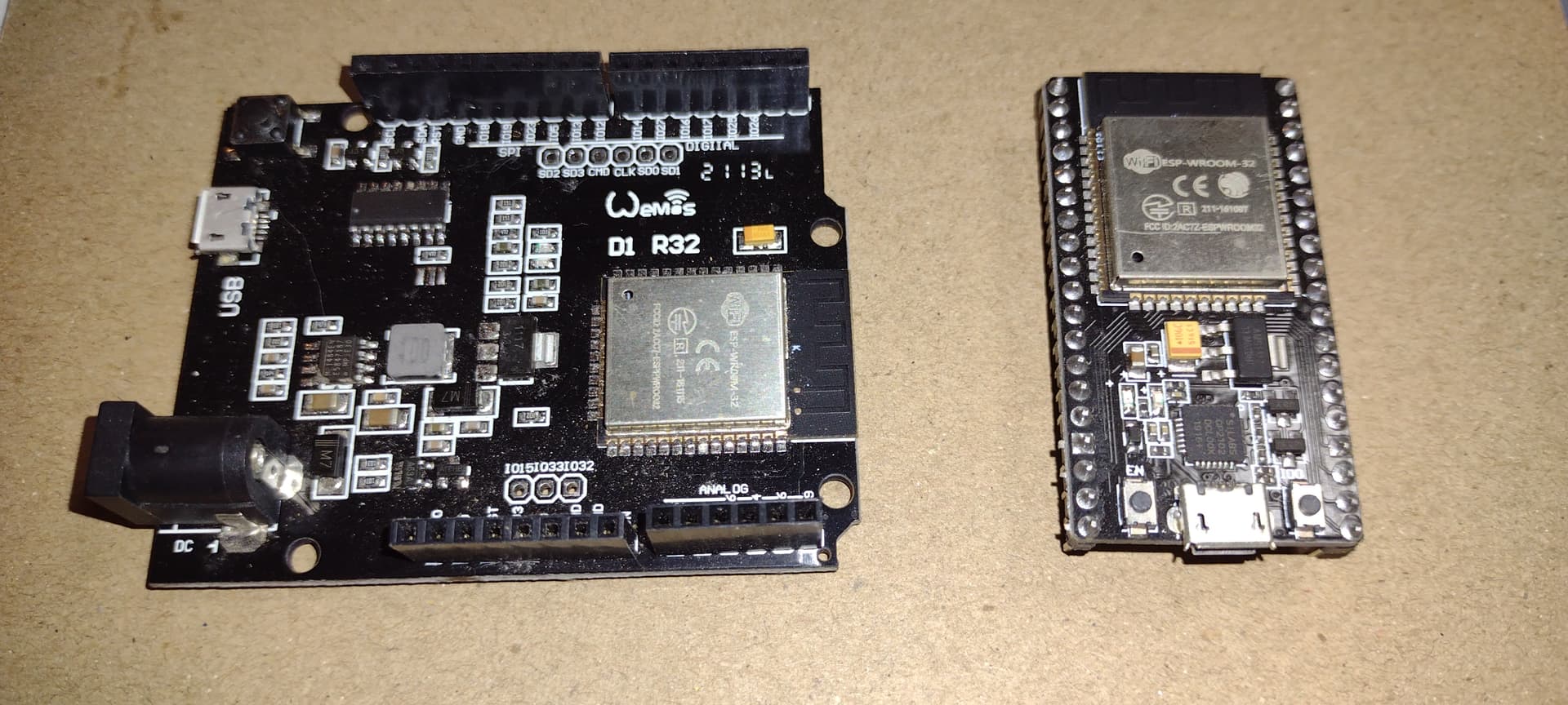
That said, perhaps it’d be a good idea to find out which ESP32 “board” he’s using
as there are many varieties available, not to mention there are at least 4 variants
of the ESP32 chip itself. e.g. ESP32, ESP32-S2, ESP32-C3 and ESP32-PICO of
which there are 3 sub-variants.
If you assume it’s a module, then there’s probably nothing that can be done other than adding more smoothing and reservoir capacitance to the 5 V USB power, assuming @nekont doesn’t have or want to use a powered hub - or has and it fails to improve matters.
That’s not to say he could be using the “raw” chip, but the modules are so widely available
and so inexpensive, it’d make little sense to try and use the chip itself.
Call me a pedant if you will, but if somebody writes ESP32, then unless there’s strong evidence to the contrary, I think it’s reasonable to take it at face value and answer the question as if it’s the device on the data sheet and not a module incorporating it.
You won’t be able to do anything with the separate supplies to the ESP32 itself, so you need to make certain that the power supply to the module can deliver enough current (as I mentioned earlier) and that it’s adequately smoothed and decoupled.
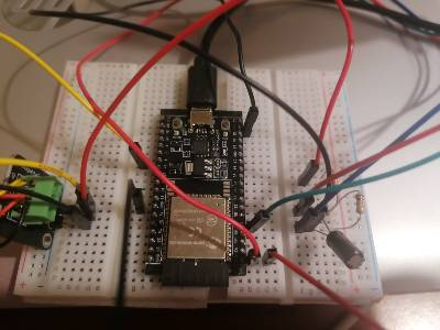
Prototype boards can often give problems, which will disappear when you transfer to a custom-designed p.c.b., and I would suggest those long wires are only adding to the problem. If possible you should shorten all those wires. Is that capacitor I can see decoupling the power supply? What value is it? You might see an improvement if you use a higher value and add a small ceramic capacitor in parallel to handle the higher frequencies.
Some thing weird happened and i dont know if you can understand why that happened.
When i changed the GND pin (at the first time i used the GND between pin 12 and pin 13) and used the GND that is beside pin 23 then i didnt have problem with the WiFi !!
Have you checked the data sheet for your particular ESP32 module? I could not identify which particular version you have. The data sheet should give you all the information you require to use the module correctly.
I would expect the two GND connections are separate, and when used correctly that will prevent exactly the sort of problem you had. What does the data sheet say about which GND to use for which purpose, and how you should connect those and the associated power pins in particular?
With complicated devices that operate at VHF & UHF frequencies, it is essential to do exactly as the data sheet recommends.