Hi guys. I want to measure the current of a cable, and I followed the steps on the “CT Sensors - Interfacing with an Arduino” page. The setup is working fine with Arduino UNO, but I want to send data to a web server, so I decided to use an ESP32. I have changed the power supply to the breadboard to 3.3V and the Burden Resistor to 22 Ω. Using pin 34 on the ESP32, but it always give 0, but I used the Arduino UNO with a 3.3 V power supply with the same circuit tree, everything works. I printout the analogRead(34), it always give me 4095
The code is
Have you searched the forum for “ESP32” and read some of the posts? Why I ask is because many people have tried to use the ESP32 to measure analogue values, and I don’t think many (if any) have found a good solution. It appears that most give up and either use a separate ADC to feed the digital data to the ESP32, or use an Arduino (and the Atmel ATMega 328P for which emonLib and emonLibCM were designed) and use the ESP32 only for sending the serial text output to the network.
I’ve never tried to use an ESP32 so I can’t offer detailed help on what might work.
However, I’ve quickly looked at Table 7 on page 22 of the data sheet, and there it gives the input voltage range of the ADC under various conditions. If you don’t have the bias voltage for your input set (by choosing the resistor values) very close to the middle of that range, you will not read the input correctly. If you have equal bias resistors and a 3.3 V supply, the bias is 1.65 V and that’s above the maximum voltage of two of the four ranges - in that case you will read 4095 (with zero current to measure). To stand a chance of reading anything, you must decide which range you will use, and design the input accordingly - the d.c. bias must sit in the middle of the input range, and you choose the burden resistor so that the peak-peak voltage developed across it at the maximum current you want to measure is not greater than the voltage range of the input.
When you have credible readings, you must adjust the sketch. The number “1480” will be wrong - I cannot tell you the correct number. It should be the number of samples that you can read in a whole number of cycles of mains power. The only way is, once your sketch is working, to time how many samples per second you get and calculate a number from that.
I’m sorry I can’t offer a ready-made solution, but I hope this points you in the right direction.
If you receive 4095 then the voltage being applied to pin 34 is greater than ~3.6-3.9v (max for defaults in arduino-esp32 using 11dB attenuation). If the attenuation is lower then the maximum voltage will be consderably lower, 0dB (default on startup!) is 1.1v.
As noted by @Robert.Wall you will need to adjust the bias voltage and the number of samples taken. I have been very successful in using the ESP32 ADCs for reading current usage using a shunt R with amplifier (INA2180 is what I’m using but other options will also work). The CT should also work similarly with the proper bias / burden.
Thank you so much for your answer. I will use a voltage divider to lower the bias voltage and see whether it will work or not. For this project, I don’t care about whether it gives me a correct Irms reading, I just need to see it has something from the reading
If you look at the diagram on this page: https://learn.openenergymonitor.org/electricity-monitoring/ct-sensors/interface-with-arduino
Your problem is for your ESP32, the “Arduino 5 V d.c.” is actually 3.3 V, and “midpoint” must be the middle of the ADC’s input range, not the middle of the supply voltage range. Taking the “Atten=0” line of the table as an example, the effective measurement range is 100–950 mV . The mid-point of that is (100 + (850 ÷ 2)) mV = 525 mV.
Given that voltage across R2, and say R2 = 10 kΩ, 52.5 µA flows down it. You therefore need a value for R1 that will drop (3.3 V - 0.525 V) at that current. I make that 52.9 kΩ approx. You should be able to get a 51 kΩ resistor (in the E24 series) which is the closest you’ll get (easily). That will lower the bias voltage a little and reduce the maximum voltage swing a little. (Or you could have 56 kΩ in parallel with 1 MΩ, which will give you 53 kΩ.)
Hi Robert @Robert.Wall
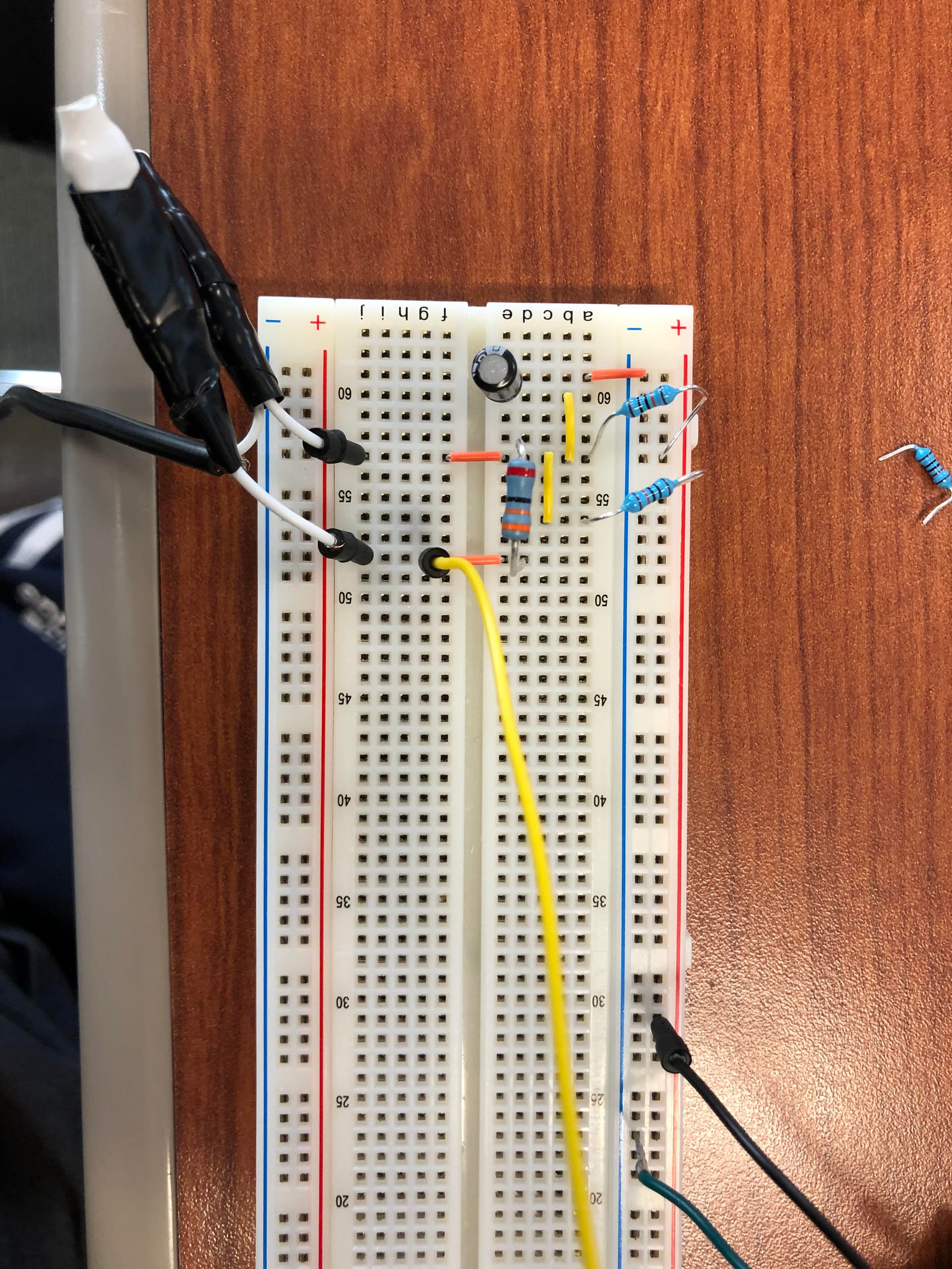
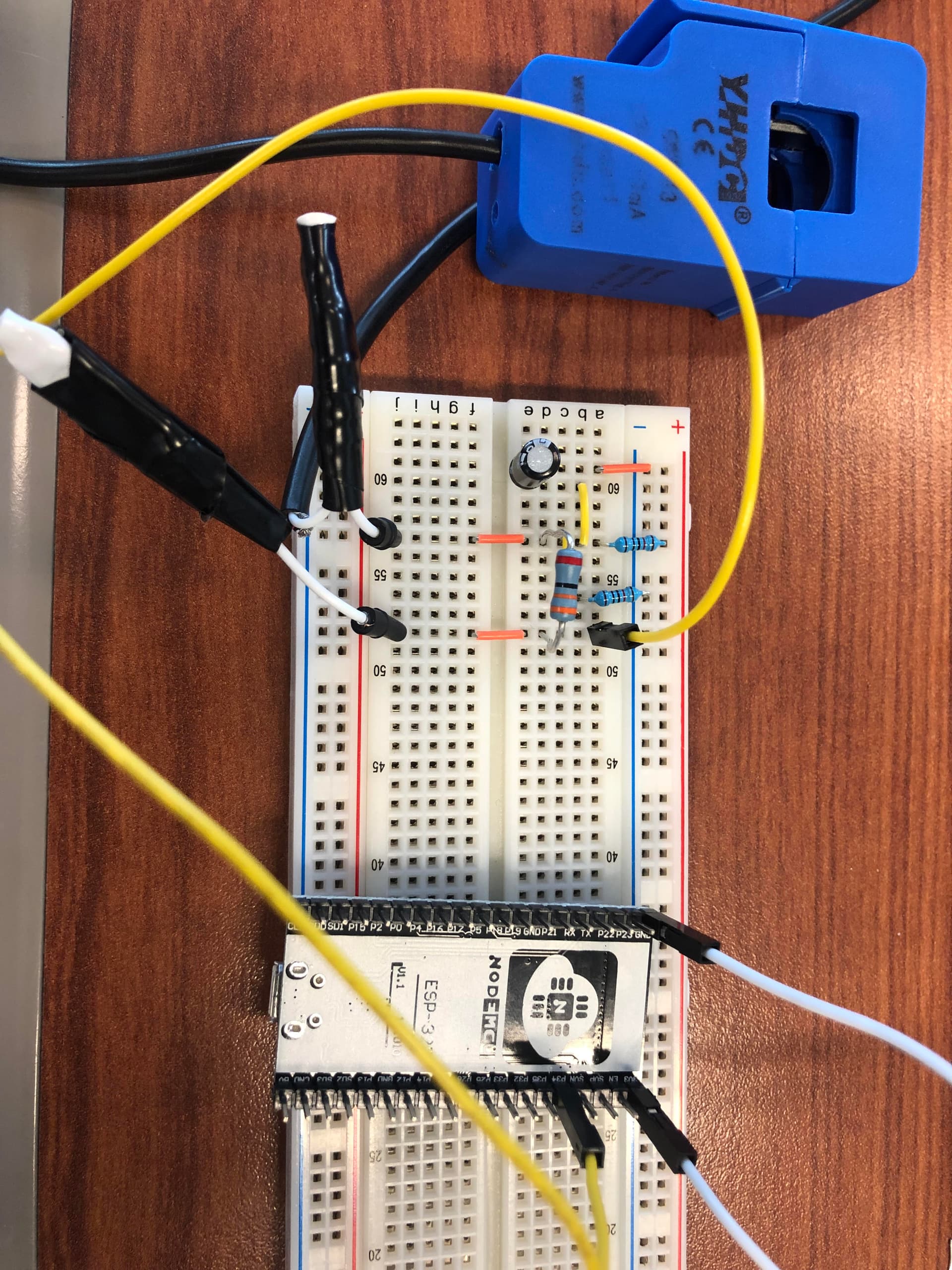
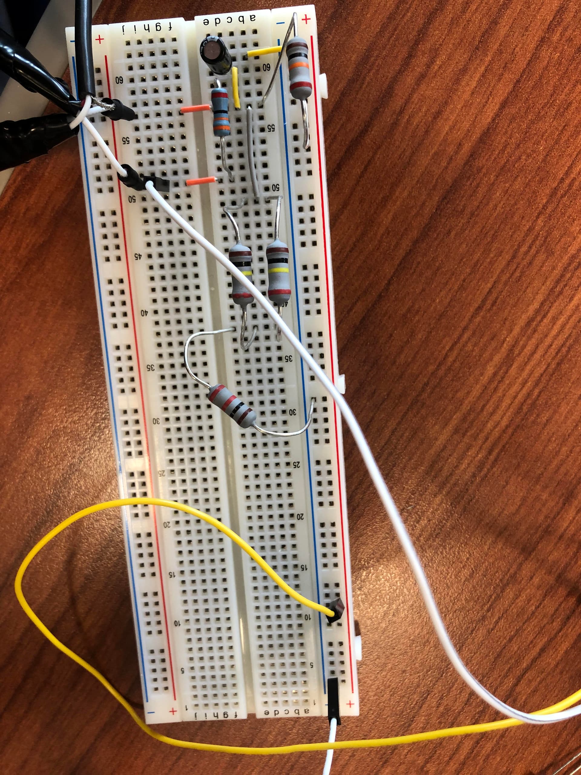
I set the R1 to 10 kΩ, and R2 to 51 kΩ by using two 100kΩ in parallel and one 1kΩ in series, but still no reading from the ESP32. Still 4095 from the analogRead(34). What could go wrong? Thanks
The following is the setup:
Read my post again, CAREFULLY this time. You have the resistors the wrong way round.
And are you using the same value for “Atten” that I chose for the example of how to calculate the resistor values? You must decide how you are using the ADC and look up the input voltage range that applies to your set-up, then calculate the resistors according to that.
Hi Robert, the following is the code I am using. Sorry, I am pretty new to this area. Thank you for your patience #include “EmonLib.h” // Include Emon Library #include <driver/adc.h>
EnergyMonitor emon1; // Create an instance
void setup()
{ adc1_config_channel_atten(ADC1_CHANNEL_6, ADC_ATTEN_DB_0); //This line is to set atten = 0, am I right?
Serial.begin(115200);
emon1.current(34, 30);
}