Hi,
Following this tutorial:
https://learn.openenergymonitor.org/electricity-monitoring/ct-sensors/how-to-build-an-arduino-energy-monitor-measuring-current-only
There seems to be an error in the diagram listed.
It lists:
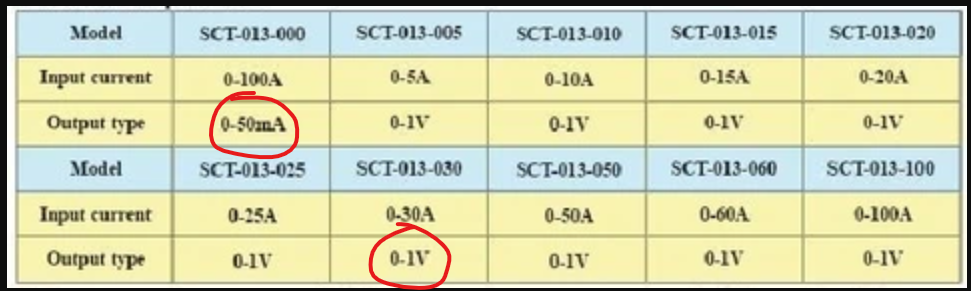
1 x CT sensor YHDC SCT-013-000
1 x Burden resistor 18 Ohms if supply voltage is 3.3V, or 33 Ohms if supply voltage is 5V
2 x 10k Ohm resistors (or any equal value resistor pair up to 470k Ohm)
1 x 10uF capacitor
However, the diagram instead has:
1x 100Ω resistor. Shouldn’t this be in place of the Burden resistor? The one that is shown horizontal.
Welcome Tom to OEM, and well spotted.
The illustration and the text are indeed inconsistent, as you point out. The 100 Ω appears in the place where the burden resistor should be - the effect of using that value would be to give a maximum for the measured current of 32 A approximately if a 5 V supply is used, or 22 A for a 3.3 V supply.
Changes and improvements to emonLib over time also mean that the sketch on that page requires some small changes for optimal results. Although it will still “work” as an illustration of the principle, the number of samples should change from 1480 to 1676, and for those in the UK, the nominal ‘centre’ voltage remains 240 V.
@TrystanLea / @glyn.hudson /@Gwil please note.
Hi.
OK thanks. If that could be updated, that would be ideal as I’m currently copying it.
Also, while I am here, I wanted to know why the SCT-013-000 was used (it outputs current rather than volt), rather than the SCT-013-030, which outputs voltage (0 to 1v). As both arduino and nodeMCU seem to accept voltage readings much simpler and easier than current?
Note, this may be the reason why ‘Savjee’ used that clip (SCT-013-030), on this project here:
Thanks.
The snag with the voltage output types is the calibration is fixed at 1 V at the rated maximum current, so you cannot take advantage of the 1.6 V rms input swing that the 5 V Arduino is capable of accepting.
All you need to convert the current to a voltage is a single component - the burden resistor. Everything else is the same.
We don’t advise trying to use the analogue input on the ESP8266 for measuring alternating voltages - many have tried but encountered various problems.