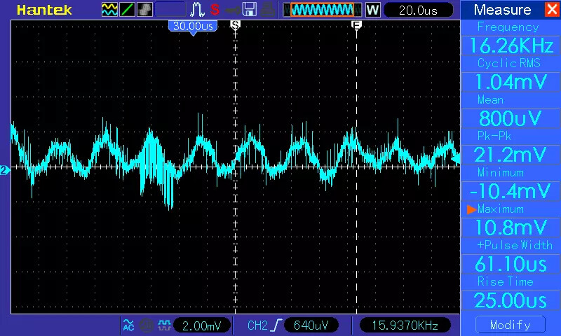
Some pictures from the “dark green pcb” emonTx4 - AREF (900 mV) :

with 1µF tantalum electrolytic from AREF to GND - about 2 mV p-p:
Here’s what the 1 µF tantalum on AREF does to the numbers (before/after):
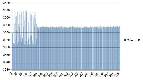
The spread of values after:
| 3585 | 3586 | 3587 | 3588 | 3589 | 3590 |
|---|---|---|---|---|---|
| 13 | 101 | 201 | 156 | 14 | 1 |
Ignoring the outlier, those represent a spread of ± 2 (±0.056%) so I’m quite content to recalibrate every mains cycle with this number.
I’m not at home at the moment so I can’t check, but from memory it’s not on the supply – I’m almost certain that’s the first place I looked.
I think I’d be inclined to adopt a configuration a bit closer to the data sheet, then divide the output down as necessary. I don’t think the noise contribution from 2 10kΩ capacitors effectively in parallel would be significant at 900 mV.