Hi Guys,… I have just done some 'rejigging on the wiring supply for my emonVs power supply,…
Initially when installed my plan was to wire the emonVs PS directly into the Aux consumer unit and feed from an internal fuse / breaker, to this end I swapped the mains supply wire for one without a plug.
However, I soon realised the a short fall in my thinking as I was hoping to use the emonVs supply as a reference into the emonPi voltage measurements,… this I found was not possible.
So my plan then changed to bring a standard 3 wire cable out to a two way socket extention, fused & fused down to max 3 Amps… so that both voltage transformers could be plugged into the EV consumer unit, and directly monitor voltage.
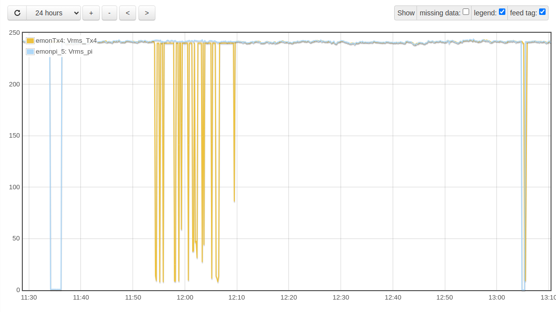
Now this is where my questions start my emonPi voltage measurement clearly shows when the transfer occured, ( as the graph drops to zero ),…
But when I removed the emonVs supply ‘from its supply’, and proceeded to rewire a new UK 13Amp standard plug to the mains supply wire of the emonVs the voltage ‘appears’ to waggle up and down ( but never to zero ) a lot,… when there is clearly No Supply voltage. So I would have expected a Zero reading.
I also performed a small test at the EV supply switch with everything connected,… a simple Off, Pause, On,… so why is there a small difference in the recorded times as shown on the graph,… and why does the emonVs supply show the voltage has only dropped to 9volts,… ( as it is actually zero ).
Is this unit working as expected, as I would have ‘assumed’ my monitored voltage would be zero when there is no input, taking into account tolerance inaccuracies.
Many Tx for any feedback
Is the emonVs the voltage reference and the sole power supply to the emonTx4?
Hi Robert, many tx for responding
Not sure,… but the emonTx4 is connected to the emonPi via the USB-C connector.
So I might assume it is powered via USB-C,… so there would be no loss of emonTx4 power during a emonVs low/loss of supply.
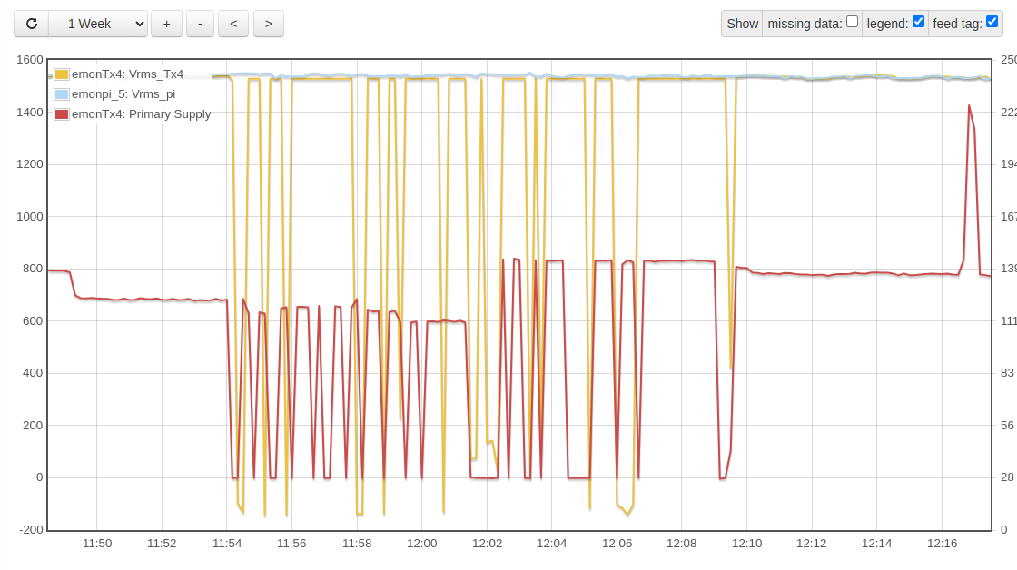
This is a screen shot of the period in question, with primary incoming supply current included,… which shows it taking samples,…
However,… this cannot be correct,… as there is always a residual 400w of power,… or more,… as my internet power is this,… But guessing this ‘maybe correct’,… as Voltage is being recorded as zero,
(Power) W=VI,… so if V = zero, W=zero…
So power supplied via USB-C I think we can say…
I had decided there must be another power supply, because the internal 5 V feed fails below about 40 V, so you’d have had nothing out, and NULLs recorded in emonCMS.
I’m a bit surprised you’re seeing as much as 9 V, though it’s quite normal to see a small voltage - I’m used to seeing anything up to one or two volts, and it’s simply pick-up. As I write, this is an unplugged 3-phase emonVs (3 phases strapped together) and uncased emonTx4 powered from my laptop:
AC missing ,
V1 = 0.47 V2 = 0.46 V3 = 0.41 f = 98.96
Pulses1 = 0  Pulses2 = 0  Pulses3 = 123
Analog in = 2056
Ch 1 I=0.045 W=0 VA=0 Wh=0 pf=0.1250
Ch 2 I=0.022 W=0 VA=0 Wh=0 pf=0.6731
Ch 3 I=0.009 W=0 VA=0 Wh=0 pf=0.2562
Ch 4 I=0.044 W=0 VA=0 Wh=0 pf=0.2462
Ch 5 I=0.042 W=0 VA=0 Wh=0 pf=0.3077
Ch 6 I=0.044 W=0 VA=0 Wh=0 pf=0.3452
The crucial bit of information, at present only used in the default sketch to switch between calculating real power and estimated apparent power when no a.c. sample is available, is “AC missing” above, obtained by a call to EmonLibDB_acPresent(int8_t channel = 1); which operates at around 17 V rms.
If you wish, you can alter your sketch to use this to force the voltage output to 0 V when no a.c. is detected.
To explain the delay, remember that the output is the average over the entire sampling period, so if the voltage disappears a few milliseconds after the start of the averaging period, it will be reported almost 10 s later. The converse is also true. Then, if you’re using a FITS feed in emonCMS, there might be another 10 s delay between the time the report arrives and the time it’s tagged in the feed.
Hi Robert ,…
Just gone into the Serial monitor,… and dumped this:-
Service-runner trigger sent for '/var/www/emoncms/scripts/serialmonitor/start.sh 115200 /dev/ttyUSB0'
Loading configuration, list (l) command sent:

Settings:
Band 433 MHz, Group 210, Node 17, 7 dBm
Calibration:
vCal = 807.86
assumedV = 240.00
i1Cal = 300.30
i1Lead = 3.20
i2Cal = 150.15
i2Lead = 3.20
i3Cal = 150.15
i3Lead = 3.20
06
i4Lead = 3.20
i5Cal = 60.06
i5Lead = 3.20
i6Cal = 60.06
i6Lead = 3.20
datalog = 9.80
pulses = 1
pulse period = 100
RF on
temp_enable = 1
JSON Format Off
MSG:9031,Vrms:241.29,P1:464,P2:4,P3:50,P4:4,P5:326,P6:9,E1:6315067,E2:376611,E3:1401354,E4:267158,E5:3174406,E6:87988,pulse:0
MSG:9032,Vrms:241.47,P1:464,P2:4,P3:51,P4:3,P5:327,P6:9,E1:6315068,E2:376611,E3:1401354,E4:267158,E5:3174407,E6:87988,pulse:0
MSG:9033,Vrms:241.27,P1:465,P2:4,P3:50,P4:3,P5:328,P6:9,E1:6315070,E2:376611,E3:1401354,E4:267158,E5:3174408,E6:87988,pulse:0
MSG:9034,Vrms:241.15,P1:466,P2:4,P3:50,P4:3,P5:329,P6:9,E1:6315071,E2:376611,E3:1401354,E4:267158,E5:3174408,E6:87988,pulse:0
MSG:9035,Vrms:241.27,P1:464,P2:4,P3:50,P4:3,P5:327,P6:9,E1:6315072,E2:376611,E3:1401354,E4:267158,E5:3174409,E6:87988,pulse:0
MSG:9036,Vrms:241.24,P1:464,P2:4,P3:50,P4:3,P5:327,P6:9,E1:6315073,E2:376611,E3:1401354,E4:267158,E5:3174410,E6:87989,pulse:0
MSG:9037,Vrms:241.14,P1:464,P2:4,P3:50,P4:3,P5:326,P6:9,E1:6315075,E2:376611,E3:1401355,E4:267158,E5:3174411,E6:87989,pulse:0
MSG:9038,Vrms:240.95,P1:465,P2:4,P3:51,P4:3,P5:327,P6:9,E1:6315076,E2:376611,E3:1401355,E4:267158,E5:3174412,E6:87989,pulse:0
MSG:9039,Vrms:241.06,P1:0,P2:0,P3:0,P4:0,P5:0,P6:0,E1:6315076,E2:376611,E3:1401355,E4:267158,E5:3174412,E6:87989,pulse:0
MSG:9040,Vrms:240.00,P1:-1,P2:0,P3:0,P4:0,P5:0,P6:0,E1:6315076,E2:376611,E3:1401355,E4:267158,E5:3174412,E6:87989,pulse:0
MSG:9041,Vrms:240.00,P1:-1,P2:0,P3:0,P4:0,P5:0,P6:0,E1:6315076,E2:376611,E3:1401355,E4:267158,E5:3174412,E6:87989,pulse:0
MSG:9042,Vrms:240.00,P1:-1,P2:0,P3:0,P4:0,P5:0,P6:0,E1:6315076,E2:376611,E3:1401355,E4:267158,E5:3174412,E6:87989,pulse:0
MSG:9043,Vrms:240.00,P1:-1,P2:0,P3:0,P4:0,P5:0,P6:0,E1:6315076,E2:376611,E3:1401355,E4:267158,E5:3174412,E6:87989,pulse:0
MSG:9044,Vrms:240.00,P1:484,P2:14,P3:66,P4:14,P5:338,P6:15,E1:6315077,E2:376611,E3:1401355,E4:267158,E5:3174413,E6:87989,pulse:0
MSG:9045,Vrms:240.00,P1:-1,P2:0,P3:0,P4:0,P5:0,P6:0,E1:6315077,E2:376611,E3:1401355,E4:267158,E5:3174413,E6:87989,pulse:0
MSG:9046,Vrms:240.00,P1:-1,P2:0,P3:0,P4:0,P5:0,P6:0,E1:6315077,E2:376611,E3:1401355,E4:267158,E5:3174413,E6:87989,pulse:0
MSG:9047,Vrms78,E2:376612,E3:1401355,E4:267158,E5:3174413,E6:87989,pulse:0
MSG:9048,Vrms:241.20,P1:508,P2:4,P3:51,P4:4,P5:316,P6:9,E1:6315080,E2:376612,E3:1401355,E4:267158,E5:3174414,E6:87989,pulse:0
MSG:9049,Vrms:241.13,P1:508,P2:4,P3:51,P4:4,P5:315,P6:9,E1:6315081,E2:376612,E3:1401355,E4:267158,E5:3174415,E6:87989,pulse:0
MSG:9050,Vrms:241.04,P1:507,P2:4,P3:51,P4:4,P5:314,P6:9,E1:6315082,E2:376612,E3:1401355,E4:267158,E5:3174416,E6:87989,pulse:0
MSG:9051,Vrms:241.22,P1:507,P2:4,P3:51,P4:4,P5:313,P6:9,E1:6315084,E2:376612,E3:1401356,E4:267158,E5:3174417,E6:87989,pulse:0
MSG:9052,Vrms:241.27,P1:510,P2:4,P3:51,P4:4,P5:314,P6:9,E1:6315085,E2:376612,E3:1401356,E4:267158,E5:3174418,E6:87989,pulse:0
MSG:9053,Vrms:241.27,P1:513,P2:4,P3:51,P4:4,P5:314,P6:17,E1:6315086,E2:376612,E3:1401356,E4:267158,E5:3174419,E6:87989,pulse:0
Looking at the output,… I my simple view,… it seems when power is switched OFF,… and the ‘spur’ to which the emonVs is connected to,… is just two floating wires,… ( with a connected earth, of course ). The recorded voltage seems to go to default,… of 240v… is this to be expected
As side note the emonPi shows the voltage drop to zero…
You didn’t say you were using the old emonLibCM sketch!
However, the same mechanism is employed - but at a slightly higher voltage, around 10% of the full-scale value. And equally you can use acPresent to force the voltage or any output to zero, if this is what you want.
When it is using the assumed voltage, then of course ‘P1’ etc are not showing real power at all, but a “best guess” at apparent power using the measured current and the assumed value for the line voltage.
Trystan produced the variants of the user sketches for the emonTx4 using either emonLibCM or emonLibDB, I have to presume he had good reasons for them working the way they do.
Forgive me Robert,… but how do I check this?? I have no idea ![]()
I can say that my emonTx4 is certainly one of the early unit sold,…
I have looked on the emonPi → admin menus and see I can update firmware to Ver1.5.7 6 chan. RFM69 ,… either LowpowerLabs, or Jeelib Classic,… which one is preferred,… Although as I use a USB connection to talk with the emonPi,… I assume this does not necessarily matter,… ( but did I read the LowPower labs is being phased out ??).
Many Tx
According to what I think is the default sketch (it’s not labelled as such), it prints either “emonTx V4 CM Continuous Monitoring V…” or “describe:EmonTX4CM” at startup.
In this case, you should probably turn the radio off. It will stop sending the same data twice to the emonPi.
I don’t believe this to be true - LPL is the latest flavour of radio comms.
Hi Robert,… tx for getting back,… I assume this is debug info displayed when the system powers up,…
Can I, ( is it ) captured info on the emonPi anywhere,… as in my hardware config,… to say the least it is not very accessible,. ( its located in my loft down the end of the house above the consumer unit,… and the CTs are all fed in via extention leads, some to consumer unit, and some to the external meter box / supply ) so unplugging all the CTs and other wires and temporarily plugging into my PC is a bit of a chore…
So can/is this info capture in anyway,… ‘remotely’,…
Also, yes my ‘Radio’ is turned off’,… and thankyou for the clarification on radio libraries,…
Looking through the docs,… on how to upload and compile,… I can see how to compile and upload the code etc on a local m/c,… and I then assume to transfer a compiled HEX file to upload from the emonPi as created from ‘export compiled binary’, as per Arduino i/f,… or is PIO the preferred compile tool i/f ?
One last thing,… I see you noted my vCal = 807.86 value, and I have seen references to other slightly different value in the docs… is this the latest current optimal value or has/is there a later s/w with improved values,… and other firmware improvements etc… just wondering
Correct. It might make its way into the emonCMS log, I don’t know. The first message is sent if you have ‘debug’ mode enabled, although “describe:” must be significant to somebody or something, I’ve never chanced upon documentation for it so I have no idea what it is intended to do.
That’s the route I took when developing the emonnPiCM, so I presume writing out to the USB-connected emonTx would be much the same as writing to the piggy-back emonTx look-alike. I did have a script to do the transfer – can’t find it just now.
Here’s my script - redacted data thus: ××××××
You will need to adapt it of course for your particular needs, the purpose of installing the key pair with no password authorises the machine (as distinct from the operator) to access the Pi, without requiring confirmation. It’s secure as long as the secret key doesn’t leak out.
#!/bin/bash

# Needs SSH enabling on emonPi / emonBase. For emonPi only, use front panel LCD menu & pushbutton. For both, add an empty file named "SSH" in the root partition.
#
# Generate a SSH key pair with "ssh-keygen" Don't set a password
# Keys are in /home/××××××/.ssh  files are private key: id_rsa; public key: id_rsa.pub
# Copy to the Pi with "ssh-copy-id [remote id]  e.g.remote-id = '[email protected].×××', password "emonpi2016" is required.
# Needs SSH & SCP on source machine. Avrdude should exist on the Pi.
#
# Old RFM12Pi with RFM69CW has 38400 baud rate for serial comms, or possibly 9600. The rest: 115200
# Programming baud rate is always 115200

remotemachine='[email protected].×××'
sourcefile='×××××/×××××/emonPiFrontEndCM.ino.standard.hex'
targetfile='/opt/openenergymonitor/emonpi/firmware/compiled/emonPiFrontEndCM.ino.standard.hex'

echo This can take about 45 seconds to complete
echo
echo Remote machine is $remotemachine
echo

scp $sourcefile $remotemachine:$targetfile

ssh $remotemachine sudo service emonhub stop

ssh $remotemachine avrdude -v -c arduino -p ATMEGA328P -P /dev/ttyAMA0 -b 115200 -U flash:w:$targetfile

ssh $remotemachine sudo service emonhub start

exit
I can’t remember now what the ‘best’ value was - I know at one point the transformer model used in the calculation was wrong, which led to a wrong value. But the differences have been minor.
EmonLibDB’s default value is 100.0 (which makes much more sense to me as there’s no calibration change required for Europe or N.America), and the constant inside the library is 8.0087, which leads me to think 800.87 might be a closer value to use. The real number to use comes from measuring the supply with a known good meter and getting the emonTx and emonPi to report the same, because while the emonTx4 and emonVs are built with components having much tighter tolerances, they can still add up to be as far away from nominal as possible.
[Edit]
A quick calculation of vCal:
The design voltage for the ADC input was I believe 0.300 V at 240 V mains, to be roughly compatible with the 0.333 V c.t’s whilst allowing headroom for the highest UK voltage of 254 V.
This is the secondary voltage of the c.t. inside the emonVs, its burden is 75 Ω so this implies a secondary current of 4 mA. The c.t. ratio is unity, which implies 4 mA primary current and 0.30 V primary voltage. The primary winding is in series with 6 × 10 kΩ resistors, so the total voltage across the emonVs input terminals is 60 kΩ × 4 mA + 0.3 V = 240.3 V.
This gives a calibration coefficient (the voltage for 1 V at the ADC input) of 240.3 ÷ 0.3 = 801
Resistor tolerances will of course affect this, as will the ADC’s reference voltage.
Inside emonLibDB, the rms count is multiplied by [the calibration value you give it = 801] × Vref [= 1.024] ÷ ADC_counts [= 4095] to change it back into volts.
Many tx for your insight Robert,… Your detailed text is much appreciated.
As I’m not sure what variation of firmware I have I am thinking / tending to a fresh compile and upload to my emonTx4,… so I will at least have a reference point for moving forward.
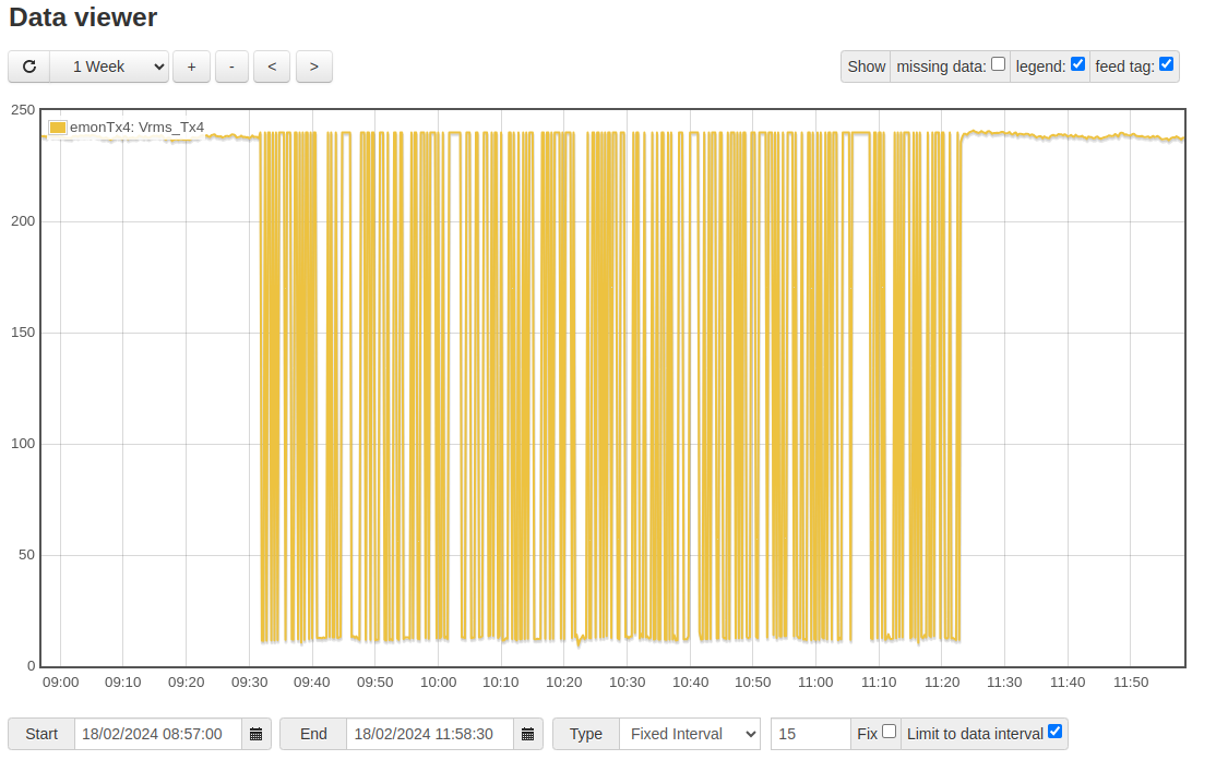
As a matter of interest,… it just so happens I have experienced a full blown power outage,… UK-Power Networks,… ( the whole village was out,… so zero volts supply ).
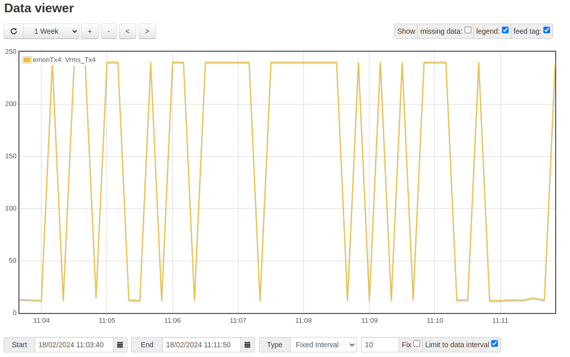
This is the result from my recorded data for that period
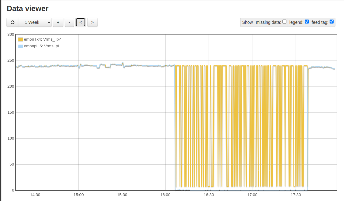
the emonPi gets the correct result,… but the emonTx misses the mark,… as far as I can deduce…
When the emonTx is showing a voltage during the outage, exactly what voltages does it give high and low? Obviously, I can’t tell from the graph - a few representative values of each state would be fine. What I’m beginning to think is you have enough pickup from adjacent wiring of whatever is powering you through the outage that it switches to ‘no a.c. input’ mode and reports the assumed default 240 V.
If this is the case, my suggestion would be for you to patch your emonLibCM to set the detection threshold to zero. If you change line 215 of emonLibCM.cpp from
unsigned int acDetectedThreshold = ADC_Counts >> 5;
to
unsigned int acDetectedThreshold = ADC_Counts >> 4;
it will double the threshold voltage, so it will hopefully show a steady 240 V, then you can also change the emonpi sketch (I don’t know which you have) where there’s something like
    if (EmonLibCM_acPresent()) {
      emontx.Vrms = EmonLibCM_getVrms() * 100;
    } else {
      emontx.Vrms = EmonLibCM_getAssumedVrms() * 100;
    }
to
    if (EmonLibCM_acPresent()) {
      emontx.Vrms = EmonLibCM_getVrms() * 100;
    } else {
      emontx.Vrms = 0;
    }
which means you’ll record a rock solid zero voltage and a vestigial amount of power calculated from the induced voltage and current.
You should not set the threshold down to zero, this will almost certainly mean it will lose all track of time (it also controls the switch from mains time to crystal) and what happens thereafter is anyone’s guess, largely depending on whatever voltage is induced into the wiring from elsewhere.
Hi Robert,… just a short/quick replay,… the HIGH = 240v and the LOW = 7.8v…
Let me get my head around the other stuff,… and get a system where I can compile from source…
I will have another play at the weekend,… isolate the EV supply ( as I use double pole isolating switch ),… and have a look with my scope what is on the lines,… appreciate this may change the result ( due to impedance etc ),… but worth having a look to get an idea as to what is been picked up on the line.
Hi Robert, more thoughts from my day,… re induced voltage,…
I don’t believe this is ‘pickup/induced voltage’,… as my entire 240vac supply network was dead,… as no power being supplied to the property whatsoever… so no source for induced voltage from 240vac systems…
As for possible induced voltage from my ‘backup supply’,… I don’t this is the case either,… as this is a low voltage 12volt DC car battery, and it supplies the emonPi,… (and is filtered locally for the Pi ), as well as WiFi access points which are separately fed via their own regulated supplies.
Or am I missing something?
Open to your thoughts,… as I scratch my head…
I don’t know, but you’re there and I’m not. All I can do is make guesses based on what you’ve written and experience. Not many people, I have a distant memory of one and I can’t recall any details, have reported a similar problem with battery backup with any emonTx, and I’m absolutely certain you’re the first with an emonVs & emonTx4. I’ve not a lot to go on.
Robert,… yes,… as they say,… I have some more evidence Ma’ Lord,… ![]()
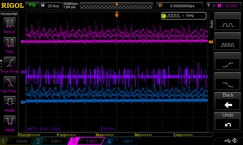
![]()
I first isolated my EV spur supply,… and measured the voltage appearing on the isolated side of the switch using a simple DVM…
This recorded as zero,… with no discernible spikes,… just a plain steady zero…
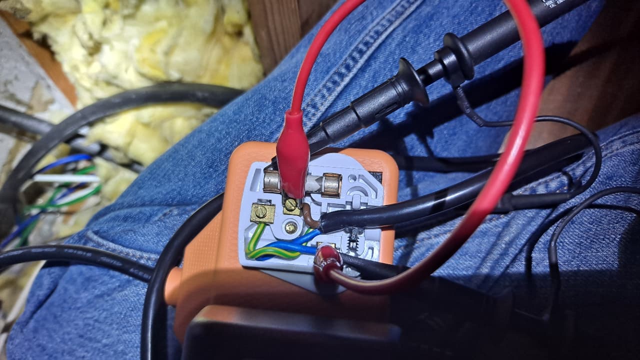
I then ‘retired’ to the loft,… and accessed the emonVs plug directly…
Knowing the wiring and the plug to be ‘dead’, I removed the plug cover to access the connections
I then attached one probe of the scope to the live connector, and the other to the Neutral connection, pls note NO Additional earth connection was made,… I was leaving that to the Neutral = ground = Earth connection,… so not necessarily perfect,… but I didn’t want my scope to become a loop to Earth/ ground etc
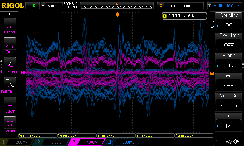
showing essentially ‘low level noise’,… IMHO,…
And then with some scope wizzardry,… I did an A - B summation…
I also checked what my ‘Feeds’ with emonPi and got this,…
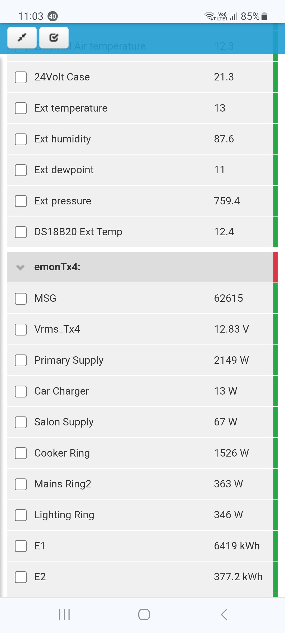
And even with a direct short across the input the displayed feed voltage did not change,… even though it was zero,… ( with the short )
Normal service has now been resumed, power restored covers back on,… etc.
Not sure what next Robert,… my thoughts are this is just being triggered by noise,… and if setting the threshold for ‘forced zero’,… maybe an option. I will look into creating a compile environment for emonPi,… ( are there any guides ,… as to what to comment out / include I have two temperature/ hum./ monitors connect via radio, BTW,… when uploading new firmware, are the CT setting saved,. else where ).
Many tx again
KR
To anyone reading this,… this is potentially very dangerous do not try and repeat if you do not understand AC power and supplies.
It looks to me as if, as I suggested earlier, it is seeing noise that is on the threshold of detection as a ‘legitimate’ voltage. When this happens, it switches into ‘real power’ mode and reports the rms value it sees – about 13 V. When the noise drops a little, it switches into ‘apparent power’ mode and reports the assumed rms voltage of 240 V. The switch is there because the same library is used for battery-only operation without a mains supply, when the only measurement available is the c.t. and so the only power it is able to report is apparent power calculated using the assumed voltage.
I must repeat the suggestions I made earlier: customise your copy of the library, then use the absence of the measured voltage (acPresent() is false) to force the sketch to report zero voltage.
What of course makes it worse is that the noise is rectified by squaring before averaging, as part of the rms calculation, so it will include harmonics that are within the pass band of the ZMPT101B inside the emonVs, and those above the sampling frequency will be reflected down and measured just the same. For the real power calculation, the noise will tend to average to zero, even if the same noise is present on the current input, because no rectification takes place until after averaging.
Yes indeed,… I was guessing it could just be a threshold issue,… But for me now, I need to get my head around PIO,… having been frustrated with the Arduino IDE for a long time,… it looks as though I will need to take the step to PIO…
Just looking through the setup steps… in the openenergy pages,… but too much for tonight, the shiraz is winning,… ![]()
![]()
But many tx for your feedback and comments,… I have something more to look at and process.
KR
You’re on your own if you do. I tried it when it first appeared - it screwed my system up, moved files around and it took hours to recover. It’s malware in my book. I’m not having it on a machine of mine ever again.
Yes, I agree the Arduino IDE is dumbed down to be almost useless for anything more than a hobbyist, but it’s less bad than the alternative.