EmonTxV3 Continuous Monitoring Firmware (v1.0-beta)

@langers2k
I’m looking for a possible cause of your stoppage. Can you tell me exactly what hardware you have;
a.c. adapter model no, which model emonTx (probably V3.4.4) or when it was purchased, and whether you have anything else connected apart from c.t’s.

From what I’ve been able to determine so far, there’s not a single obvious cause.

As I mentioned above, it’s an emonTx 3.4 with the provided UK AC-AC adaptor to power it. There are 3 CT’s (SCT13) and no other items connected. All bought together from the shop in July 2019.

I’ll confirm the exact part number on the AC adaptor tomorrow or Monday when I’m home. I assume the emonTX PCB will have 3.4.4 (or similar) on it somewhere?

I built the firmware using the Arduino IDE and the same library versions as you have, or at least it was the last commit in each library before the date you mentioned, and it survived about 3 days before it stopped broadcasting.

Does it provide any useful logs as default as I should be able to connect a serial port if it’s helpful.

I think that’s enough. If bought in July, it’s almost certain to be a 3.4.4 (though it says 3.4.3 on the silk screen).

Connecting to the serial port won’t help, all it sends is the same data that’s broadcast. There’s not enough memory for logging and such, and it wouldn’t survive the reset anyway unless written to EEPROM (and there’s precious little of that).

What I’ve found so far is it doesn’t appear it’s voltage on its own, nor temperature on its own, but it does look very much like a power supply issue. I set one up for test powered only by the a.c adapter, and it failed twice, the first time in the wee small hours, the second time within 45 mins. But with a 5 V d.c. supply and at an ambient going down from 8.5 to 6.5 °C, it’s run for 24 hours and still going. And it ran for 5 weeks during July and August on the a.c. only power. For the last few days, it’s also had a temperature and an optical pulse sensor attached.

The AVR will almost certainly still be running and is probably stuck in a loop waiting for some external h/w to complete some transaction that’s never going to happen. I had a very similar situation a few years back (on different h/w) when a Vcc glitch was causing the BOD that monitors the Wiznet ethernet chip to reset it, while the internal BOD monitoring the AVR was set to a much lower threshold so wasn’t resetting. The Wiznet driver was in an indefinite loop waiting for the Wiznet to indicate a transaction had completed but that was never going to happen because the Wiznet had been reset mid-transaction. I’d start with the Jeelib code to see if there are any SPI polling loops that wait forever. If you can probe up the SPI bus while it’s hung, you may see lots of activity.

Increasing the AVR BOD threshold might help - that will at least cause the AVR to reset… assuming you can set it higher than the BOD in the RF module. How successful that will be depends on whether or not a freshly reset AVR can soft reset the RF module (in case it didn’t reset). Ideally you want the CPU BOD to be the most sensitive (have the highest V threshold) and for it to have a GPIO pin it can use to hard reset all external devices.

The AVR’s h/w wdog can also break you out if it is a loop as in the case described above. It has a mode where it generates an interrupt first - allowing you to capture state into non-volatile storage - and then generates a /RESET. Or you can even just stay in the ISR, continuously printing out state and patting the wdog to prevent the second stage /RESET.

Of course all of this only helps in the recovery, it doesn’t solve the root cause. But it can help determine the root cause.

Any variables you put in the .noinit section will be unmolested by the zeroing of .bss at start-up, so they’re somewhat non-volatile but they obviously won’t survive a full power fail. Just a single variable reflecting which bit of code you were in could be a good starting point. Here’s what I do in one of my sketches…

void loop () {
  while (1) {

    last_pid = 0xdead0001;
    process_wdog();

    last_pid = 0xdead0002;
    process_energy_monitors();

    last_pid = 0xdead0003;
    process_pulse_counters();

    last_pid = 0xdead0004;
    process_tank_inputs();

    last_pid = 0xdead0005;
    process_leds();

    last_pid = 0xdead0006;
    process_temp_sensor();

    last_pid = 0xdead0007;
    process_network_layer();

    last_pid = 0xdead0008;
    process_host_requests();

    last_pid = 0xdead0009;
    process_ram_monitor();

    last_pid = 0xdead000a;
    process_uptime();

    last_pid = 0xdead000b;
    process_waveform_data();

    last_pid = 0xdead000c;
    process_maintenance_requests();

  }
}

That’s my initial assumption, with the guilty party most likely being the RFM69.

I do know that’s the case - there is at least one loop in the JeeLib code that waits for the hardware and has no timeout. It’s that one that causes a lock-up if the RFM is missing or not soldered in properly, so I’m prepared to bet the same thing is happening here.

My first trick was going to be to see what happens to the regulator voltage whilst transmitting, as that’s when the maximum power demand occurs. Then watch as I wind the a.c. voltage down…

But I won’t be doing that for a few days, because I’ve got a test running using the 5 V USB d.c. power, and so far it’s not locked up whereas it failed twice in 24 hours at 8.5 °C or lower ambient with the a.c. only power. It’s showing a temperature of 5.8 °C at present.

@glyn.hudson just introduced a watchdog to the discreet sampling firmware before we switched to the CM firmware, perhaps we should introduce the watchdog on the CM firmware as well rather than needing to dig into and debug jeelib?

I’ve created a branch that introduces an avr watchdog here and am testing: https://github.com/openenergymonitor/EmonTxV3CM/compare/watchdog

The problem with the watchdog when you’re using the library to accumulate Wh is those will zero if/when the watchdog resets.

@dBC suggested that the watchdog might fire an ISR - conceivably that could write the energy values to EEPROM and the sketch could recover them at start-up. I’ve no idea whether that’s possible or feasible.

But the priority is to understand why the lock-up is occurring rather than to hide the symptoms.

If JeeLib is the problem, does LowPowerLib do the same? Or, as dBC also suggested, can the brownout on the AtMega be set higher so that it fails and does a reset (but that still leaves the problem with the energy values).

That would be nice, agreed the Wh reset is an issue - but fixable with the Wh Accumulator process as long as they are not too regular.

Sure, though we can use the resetting of the message count (and wh accumulators) as our indicator that the problem is persisting if we did introduce the watchdog as well.

That’s close to what I do, except I preserve machine state (including the offending PC of the hang) to external FRAM rather than EEPROM. The internal EEPROM is only good for 100K cycles so if there’s any chance it can get into a mode where it happens continuously, you might need to throttle back to avoid wearing the EEPROM out. I’ll attach my code below in case it’s of any use (much of it is specific to my system and can be ignored).

I just checked the datasheet for your 328P and it looks like the BOD only has three settings: 4.3V and 2.7V and disabled. It’d be interesting to know whether you guys have it set to 2.7V or disabled. And the 2.7V is nominal, it can trigger anywhere from 2.5V to 2.9V and needs to remain below the threshold voltage for tBOD before it triggers. Mysteriously tBOD is referenced but not specified in the 328P datasheet I have. For reference, in the 2560 that I’m more familiar with, it’s 2 usecs.

It looks like your device is spec’d to run fine all the way down to 2.7V, but only at 8MHz. I vaguely recall you guys are already overclocking it even at 3.3V. I run my 2560 at 8MHz and 3.3V, and set the BOD to 2.7V.

How do you deal with that in the case of a real power failure?

If you set the AVR BOD to trigger early the other potential issue to deal with is that it only resets the AVR, not the entire board. So your AVR code will start afresh at init() but that code may well assume that all the external h/w has also just come out of reset and is in virgin state. Depending on the nature of the Vcc glitch/sag and the various BODs in all the devices, that may not be a valid assumption - the RFM module might still be in mid-transaction from the AVR’s previous life. The approach I take to that is to have a processor GPIO output pin /RESET_EXT_DEVICES that drives all the /RESET pins on the external devices. Then when the AVR starts a new life it always bangs on that pin so it knows all the external devices are also fresh out of reset.

//
//  Now that the actual ISR has carefully fetched the stack pointer from the stack
//  frame, we can go all gung-ho with further stack usage and implement the guts
//  of the wdog ISR, which is basically to preserve machine state to FRAM.
//
static void __attribute__ ((noinline)) wdog_isr_guts (uint32_t *stackp)  {

  uint32_t prog_counter, pc_swapped;

  prog_counter = *stackp;                  // fetch it off the stack

  //
  // Perversely, the AVR uses big-endian for the return PC on stack and little endian
  // for everything else.  On our 2560 the PC is 3 bytes wide, so we swap around byte0 and byte2,
  // leave byte1 where it is, and zero byte3.
  //
  pc_swapped = (uint32_t)((prog_counter & 0xff) << 16) |
    (uint32_t)(prog_counter & 0x0000ff00) |
    (uint32_t)((prog_counter & 0x00ff0000) >> 16);

  //
  // Next, all AVR instructions are multiples of 2-byte words long (typically just one 2-byte word long).
  // The PC is a word pointer, but the gcc listings and maps are all byte based, so we times by 2 here
  // so our displayed PC matches what's in the link maps and disassembly listsings.
  //
  pc_swapped *= 2;

  //
  // Update the health report block with wdog info, and write it out to FRAM for
  // reporting in our next life.
  //
  health_report.wdog_portc = PORTC;
  health_report.wdog_porta = PORTA;
  PORTA = PORTC = SEL_NOBODY;          // Give everyone plenty of time to get off the bus 
  health_report.wdog_pc = pc_swapped;
  health_report.wdog_fw_version_maj = FW_MAJOR_VERSION;
  health_report.wdog_fw_version_min = FW_MINOR_VERSION;
  health_report.wdog_link_status = link_led_shadow;
  health_report.last_known_pid = last_pid;
  write_fram_block(0, (uint8_t *)&health_report, sizeof(health_report));
    
  //
  // Prepare for death
  //
  cli();                            // In case we call it from somewhere other than ISR
  while(1);                         // Wait for the 2nd bite.
}

//
// The wdog has been set up to generate an ISR on the first firing, and a
// reset on the second.  This is the handler for that first firing.  This ISR
// never returns, so we don't have to preserve any system state.  By going NAKED,
// we disable all prologue which means SP is pointing to the first free byte of
// stack, just 1 byte below where the PC has been stored.  We want to get that
// PC to help determine where the hang is.  The one thing we really do want from
// the missing prologue is the re-zeroing of r1.  If the interrupt happened to fire
// just after a MUL instruction, then r1 will be non-zero, but the compiler assumes
// it will always be zero.  We brute-force it back to zero here, just in case the
// code in the guts() routine requires it.  Again, we don't care about preserving its
// old value, because we're never going back.
//
ISR(WDT_vect, ISR_NAKED) {
  register uint8_t *stack_pointer;             // user 'register' to avoid allocating more stack

  asm("eor __zero_reg__	, __zero_reg__"::);    // ensure r1 is zero, normally done by isr prologue
  stack_pointer = (uint8_t *)SP;               // fetch the current stack pointer
  stack_pointer++;                             // back up one byte to return PC
  wdog_isr_guts((uint32_t *)stack_pointer);    // let guts treat it like a 32-bit entity
  while(1);                                    // wait for the reset to happen, if guts doesn't
}
Unfortunately, only the EEPROM is available on the emonTx.

I’d looked at that - clearly with a 3.3 V supply, options are limited :thinking: and there’s no clear indication of what happens with the RFM, although it works down to 1.8 V. One would hope that if the supply goes below that, it recovers cleanly.

Apart from the voltage regulators, the AVR & the RFM are the only two active devices.

The reset on the RFM is not used.

I’m working on the assumption - to be verified - that the 3.3 V rail crashes for a matter of a millisecond or less. A real power failure (even an auto-recloser) is likely to last longer - long enough for the supply to collapse far enough so that everything starts afresh. Unfortunately still starting the accumulated energies from zero. As Trystan notes, emonCMS is able to handle that…

(I don’t understand that caveat though.)

If emonCMS can handle the reset accumulated energies from a real power failure then presumably it can handle them from a reset as well (be it a wdog reset, BOD reset, or even button reset).

But if you did want to try to eliminate that for the reset case, you could experiment with the .noinit section. Variables located there don’t get re-initialised as a result of a reset, they retain their values from the previous incarnation.

The downside is they also don’t get initialised (or zeroed) after a real power failure, after which their contents could contain anything. With enough signature bytes and CRCs wrapped around them, you can be reasonably confident you won’t interpret random bytes as meaningful data left behind by the prior incarnation.

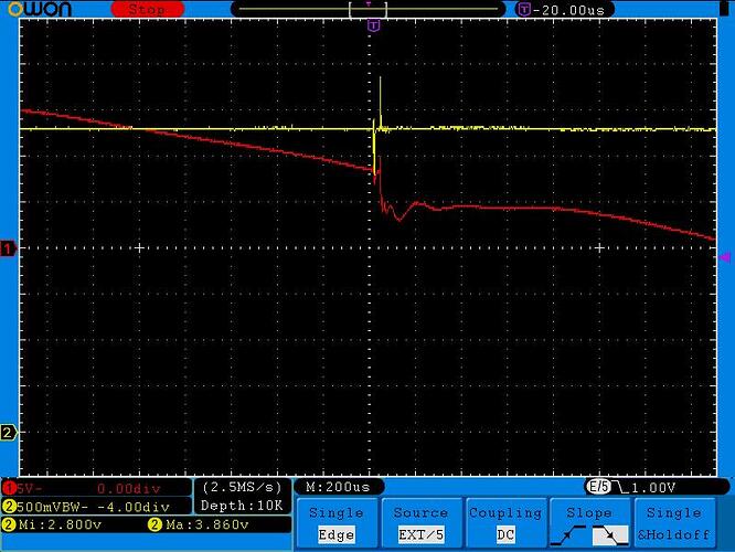
I was looking for an old unrelated scope trace and happened across the one relevant to my Wiznet BOD hang described above, so thought I’d share. It took months to track this one down because it happened so rarely and apparently randomly, but one day by chance I happened to notice that it appeared to happen at the precise moment I put the awning out (which has an AC motor to drive it). Playing with that a bit I found that about 1-in-10 motor starts would trigger it. Suddenly something that seemed quite random had a pattern to it.

Red is a proxy for the main voltage (the output of an AC wall-wart driving nothing but the scope lead) and Yellow is Vcc. Both the awning motor and the device under test were on the one breaker, with the awning motor at the end of a fairly long run. Depending on where in the cycle the motor came on, it could put a pretty big divot in the mains on that branch. Despite a lot of decoupling it messed up Vcc enough to trigger various BODs on the board. This was using a small PCB mounted SMPS module, so quite different from your design, so maybe not relevant.

That mechanism is also one that I’d considered - and it’s quite possible that the same sort of thing - a momentary dip - is happening.

Am I reading that picture correctly, and there’s a 600 mV spike each way on Vcc?

Yep, pretty close. Actually the scope measured the Min and Max on the Yellow as 2.8V and 3.86V.

The problems appears to be linked to JeeLib and the RFM radio. It doesn’t appear to be related to undervoltage, temperature or any other obvious cause.

During my recent tests, two failure modes occurred.

  1. The one reported where transmissions ceased, and a press of the reset button was needed.
  2. One not reported, where the message count and energy totals were reset to zero but transmissions continued.

The second happened very frequently, though neither had been seen in the original testing in the summer of 2018.
I established that the first fault happened whilst waking the RFM, transmitting the data and sleeping the RFM again.

I replaced the “full” JeeLib with a cut-down ‘transmit-only’ version, and that appears to have provided a significant reduction, if not a total removal, of the problem. The full details are here: EmonTx stops sending data - no led activity until reboot - #18 by Robert.Wall

Note the warning about the higher risk of r.f. collisions.

1 Like

I’m interested in this, but am admittedly not up-to-speed on which EmonTxV3 is which!

So, apologies if this is a stupid question but I have a TxV3, and was wondering if there was a way of checking which specific chipset it is via software rather than cracking open the case and looking at the circuit board?

There’s basically no way of telling without looking at the PCB. All use the same processor. So unless you can see inside and see enough detail, you need to get the PCB out.

The V3.2 uses the RFμ328 which has the processor on a “piggy-back” circuit board with the RFM12B radio module piggy-backed on that, and has no DIP switches. The V3.4 has the processor mounted directly on the main PCB and does have DIP switches, but can have either a RFM12B or a RFM69CW radio module fitted. Only the early V3.4 had the RFM12B, which won’t work with the rfm.ino code from the 3-phase sketch.

But the CM library itself will work on anything - even the emonTx V2. (A lot of the development was done on a V2 because of all the spare I/O I could hang a 'scope on to check the timing etc.)

@Robert.Wall thanks - so I could “just apply this and it would work???”

Regardless, I’ll open it up tomorrow and take some pics…

I’m a little nervous about just clicking upgrade because of some other posts.

You can’t click “upgrade” anywhere to change the software in an emonTx, it’s a bit more involved than that. Clicking “upgrade” sounds as if you’re talking about an emonPi. If you are, it’s absolutely certain that you can’t apply that change to it.

If you are talking about an emonTx, then although the library will work on all versions, it’s not a ‘drop-in’ replacement, as you’ll see from the documentation that comes with it in the zip file. You’ll need to modify your sketch following the example sketches.