Hello,
I have two questions around the values i’m getting from my EmonTx.
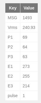
Firstly, the EmonESP interface is providing power values for all 3 CTs (P1, P2 & P3), along with Voltage measurement (Vrms), but there’s also values for something labelled E1, E2, E3 are these Energy values (watt-hours)?
Secondly, all 3 CTs are measuring the same thing, but there is a difference of 6 Watts between P1 and P3. Another thing to note is that I have a separate meter which is displaying the power at about 58w. The CTs are 100A CTs on a line which is only using about 0.2A. Considering that the current is so low should I be concerned that the CT measurements aren’t close to each other or the separate meter? Is it worth my time trying to calibrate the EmonTx?
I don’t have an ESP8266, however I believe the “E” values are indeed Wh.
No. C.T’s are inherently inaccurate at low currents. The SCT-013-000 is only specified for accuracy above 10 A. It’s probably more phase error than amplitude error that’s affecting the real power calculation.
It may well be, if you have a sufficiently accurate meter. When I tried to do the maths and a Monte Carlo analysis, I came to the conclusion that for any one input, 45% of emonTx V3.4.4 production would be inside ½ %, and 82% of emonTx V3.4.4 production would be inside 1 %. This of course doesn’t mean that all the inputs of yours are within 1%, it could be one or all of them are in the 18% that are outside this.
It may well be, if you have a sufficiently accurate meter.
I have a WattsUp Pro in the middle of the line which i’m using to compare voltage, power and amps of the emonTx. I used a Fluke 325 to confirm the Amps of the WattsUp too, I would use it to confirm Voltage too, but that’d require sticking prongs into the socket and I’m hesitant to do that.
I tested the values of another EmonTx and EmonESP on the same line and it had the same level of inaccuracy so I’d say it’s just because there’s such little current on the line.
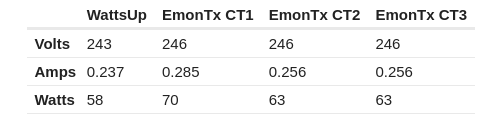
I wasn’t sure if the inaccuracy came from the Voltage or from the CT readings so I had to take some measurements and test it. After some minor testing the issue does seem to be with the CT measurements. The WattsUp meter measures 0.237 A and the CTs seem to measure 0.256 - 0.285 A. There is a difference in Voltage measurements, but the difference in Amps seems to significantly affect the Power values, see the table below.
WattsUp
EmonTx CT1
EmonTx CT2
EmonTx CT3
Volts
243
246
246
246
Amps
0.237
0.285
0.256
0.256
Watts
58
70
63
63
Note: The EmonTx doesn’t return Amps so I had to calculate it with A = W/V
So there is a noticeable difference in Voltage measurements and I wanted to see if using the WattsUp Voltage with the EmonTx Amps would return a more accurate Watt value, but it didn’t
243 * 0.285 = 69 w (1 less than original)
243 * 0.256 = 62 w (1 less than original)
Next I tried using the WattsUp Amps with the EmonTx Voltage which produced a Watt value closer to the WattsUp pro.
246 * 0.237 = 58 w
So if i was to calibrate it, I’d have to adjust the CT readings and not the Voltage readings, which is good to know.
Let me know if this makes sense or if I’ve missed something.
I do it all the time, but then I’m professionally qualified in Electrical Engineering and know the risks.
But it does calculate it - if you have a programmer, you could tweak the sketch to display current.
As I wrote, c.t’s are inherently inaccurate at low currents, so I’d look at it this way: an error of 50 mA represents 0.05% of the maximum for the c.t, and 0.33% (if what little information I could find from your link is correct) for the Watts Up. What is the specified accuracy for that at this power/current?
I think what you’re missing is you’re expecting both the c.t. and the emonTx to perform way outside their expected operating range. If you spent a lot more money on an instrument-grade or revenue-grade c.t., it would be guaranteed down to a lower current than 10% of full load. It would probably also perform better at all loads but particularly at lower loads. If you choose a c.t. that is rated closer to the current you’re actually measuring, then you can expect the rated accuracy.
If you need accuracy at those currents and must keep the SCT-013-000 (I’m assuming that is the case although you haven’t confirmed it), consider a multi-turn primary winding for your c.t. That will of course lower the maximum current in proportion to the number of turns, you must also change the calibration by the same ratio. For example, if you only need to read up to 16.66 A, use a 6-turn primary winding and change the current calibration constant to 15.15. I would expect the numbers to be closer, but even so, the c.t. is still working outside the range over which accuracy is specified. To get inside that, you need a 45-turn primary winding, giving you “full scale” current of 2.2 A.
I think what you’re missing is you’re expecting both the c.t. and the emonTx to perform way outside their expected operating range.
This is true, but this low power measuring isn’t the intended use, when they were originally purchased. They’re meant to measure power on a 3 phase line (using the 3-phase firmware) but due to COVID19 they’re stuck at home measuring an old PC I have laying around.
If you need accuracy at those currents and must keep the SCT-013-000
Yes and no. Primarily they’ll be monitoring 3-phase lines in a remote location, but I’ll also have a small setup for testing locally before any updates might be added to the remote devices, so using the same CTs would be ideal. I might just put up with the inaccuracy for now as what I’m gathering from your post is that this inaccuracy shouldn’t be a problem when dealing with larger loads.
consider a multi-turn primary winding for your c.t. That will of course lower the maximum current in proportion to the number of turns, you must also change the calibration by the same ratio
If I was to use smaller CTs would there have to be much similar changes to the firmware?
If the c.t. you might use has a 50 mA secondary, and you’re not overly concerned with seeing the correct value, then all you need to do is multiply the reading you see by the appropriate number. If it doesn’t have a 50 mA secondary, then using it might actually be worse unless you also change the burden resistor to suit and it’s capable of generating the 1.1 V necessary to fully use the input range of the ADC. So no easy answers, I’m afraid.
If you need to test locally, then for what it’s worth I use a 6.5 V 30 VA isolating transformer on the end of a Variac and up to 20 turns for the primary winding. That way, I get 100 A at the cost of about 30 W of power, dissipated in a power resistor on a heatsink.
I can measure the phase error of the c.t. that way, but I can’t calibrate the emonTx for phase error because of the additional phase shift added by the isolating transformer and Variac. To set up the phase calibration on the emonTx, I still use the 20-turns, but with a 250 W heater direct on the mains, giving me effectively about 20 A.
I’m using the SCT-013-000 CT which has a 50 mA secondary winding if I’m not mistaken.
If you need to test locally, then for what it’s worth I use a 6.5 V 30 VA isolating transformer on the end of a Variac and up to 20 turns for the primary winding. That way, I get 100 A at the cost of about 30 W of power, dissipated in a power resistor on a heatsink.
So you have a VARIAC plugged into the mains, an Isolating Transformer plugged into the VARIAC and then a Power Resistor on a Heatsink plugged into the Isolating Transformer? and with that you can generate 100A for 30W?
To set up the phase calibration on the emonTx, I still use the 20-turns, but with a 250 W heater direct on the mains, giving me effectively about 20 A.
I’m a little confused, where is the EmonTx in this scenario and what do you mean phase error?
Exactly. 5 A @ 6.5 V ≈ 30 W; 5 A × 20 turns = 100 At ≡ 100 A × 1 t.
For almost any transformer, the output is displaced from the input - this is its phase error. (Generally, the better the transformer, and particularly if it’s designed as a reference source, the less the phase error.)
When I’m measuring the phase error of a transformer, the emonTx doesn’t appear in the picture. I record the waveforms either with a sound card or a digital 'scope, then analyse in a spreadsheet to extract the 50 Hz component and measure the phase difference between input and output.
then the setup is very much as for a standard emonTx installation - emonTx, a.c. adapter, c.t, resistive load but × 20.
Exactly. 5 A @ 6.5 V ≈ 30 W; 5 A × 20 turns = 100 At ≡ 100 A × 1 t.
This might be a better option than messing with the EmonTx firmware, something I’ll definitely look into. Would you recommend the VARIAC you’re currently using or would you suggest something else? I might as well ask if you would also recommend the Isolation Transformer and Power Resistor you’re using also?
Would I be right in saying that the CT is measuring the line between the Isolation Transformer and the Power Resistor?
Is the voltage reference for the EmonTx plugged into the Isolation Transformer too?
I had the Variac and the transformer to hand (recovered from scrapped equipment). The purpose of the Variac is to be able to set the input voltage to the isolating transformer, hence its output voltage, hence the current. With a combination of that and the turns through the c.t., and an additional series resistor for very low currents, I can set any current (really ampere-turns) from about 100 mA to 100 A reasonably easily. I don’t go below 100 mA because the c.t. output voltage with our standard burden gets very hard to measure reliably.
Yes.
If you (or your firm) is buying new, then you design for what you want. You need enough voltage to be able to put an ammeter/digital multimeter in series to measure the current (CHECK - they often drop 200 mV or more), and you need enough current to not need a stupid number of turns - but not too much as to make the wire size difficult. Apart from reducing the power, the low voltage means safety (from voltage) isn’t a worry.
What I had happened to be very convenient.
Details are in ‘Learn’ in the c.t. test report. Although the transformer is actually rated at 8 A, setting the design maximum test current at 5 A is convenient, especially as I had a 5 A MI meter that is very useful for roughly setting the current quickly (much better than a digital meter).
No, if you’re not interested in the phase error, the v.t. is connected straight onto the mains, when the emonTx shows power up to 24 kW or so (with the 100 A c.t.). If you are interested in phase error, you can’t use the Variac and step-down transformer, so that has to be done purely with turns through the c.t. if you need to vary the current - unless you can lay your hands on something like an old rheostat-type stage lighting dimmer!
What is it specifcally, that’s made you reluctant to probe the socket?
I’m a software developer, not an electrical engineer, sticking metal things into sockets seems dangerous to me and I’m not sure if there’s something else I’d need in order to do it safely.
Completely understandable, as it can be dangerous if one gets in a hurry or goes about it in a
wreckless manner.
I’m not recommending that you do something you’re not comfortable with.
If you’re still don’t feel comfortable doing it, then by all means don’t do it.
But if you excercise care and don’t get in a hurry, that goes a long way in avoiding problems.
To answer your question regarding if anything else is needed… your meter and a bit of care and
patience should be all you need.
I’ll definitely check that out. It does seem like a nice setup to have, the only question is if the work involved is too complex or not for a lowly software dev like me. There may be colleagues who could assist or point me in the right direction for assistance, but that would most likely mean waiting until we’re back in an office environment. For now, I’ll put up with the inaccurate values, read up about your test report and plan for what we’ll need.
I’m also curious if there is a simple device that draws enough power to produce a few Amps, something >0.5A at least, it might be a temporary solution?
If you don’t want to handle mains voltages, there’s nothing that immediately springs to mind. If you were replicating my test rig, you’d be getting the components from the likes of RS Components or Farnell/CPC, and by the time you’ve added it all up, it wouldn’t be cheap.You won’t see any change out of £120 just for the Variac, isolating transformer and heat sink.
If you are looking for something simple to do at home, then you’ve got little choice but to use the mains supply. For the load, you’re looking for something like convector heaters, oil-filled radiators, electric kettles and the like that will guarantee a nice clean waveform; the difficulty you face is getting at the wiring to put a c.t. on - and ideally with multiple turns available so that you can multiply the current.
If you’re doing it as a “semi-permanent” test rig, I’d get a cheap multi-socket extension lead, chop the cable in the middle and put the ends into a junction box, and bring out a length of single-core wire that you can put the c.t. on, with enough length to have a good number of turns. Then you can plug whatever load or loads you have available to get the varying currents.
But again, you need to take a lot more care if you have mains voltages. The beauty of my rig is I don’t care if I touch anything - as long as I keep my fingers off the load resistor, which gets quite hot. The side I’m handling all the time is 6.5 V. The mains side is as shrouded as I can make it - but it’s still possible to touch live metal if you try hard.
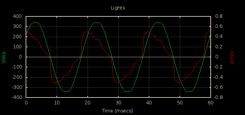
Interestingly, all 4 of them
clock it very close to unity power factor which is impressive for an old PC. Do you know if the PC has a power factor correcting power supply? I checked a few old ones I had, and the best power factor I found was about 0.88. The current signature for that one looks like:
My monitor clocked that at 244.2V, 356mA, 76.5W, -36.9VAR (reactive) and 19 VAR (distortion)
I notice the specs on the Watts Up Pro include: Below 60 watts, current and power factor decrease in accuracy, although they don’t say how much, but it sounds like you’re reaching the lower limits of both of them.
Apologies for late response, busy week. I’m not sure if it does or doesn’t but if you’re still curious then there’s some links I found when I search for the model number (FSP250-60HEN). This PC is more than 10 years old so I don’t know if a new PSU will behave the same way.
Thanks for the model number… I found several links stating that power supply does indeed have active power factor correction, and judging by your measurements above it’s working well. Looks like you Europeans mandated that way back in 2001.