Hi, I have an EmonTx v3 433Mhz which has been running for 2 1/2 years with the data sent to a RPi “Powered by openenergymonitor.org | v8.1.2 (from apt)” and a RFM69Pi 433Mhz Raspberry Pi Base Station Receiver Board.
I installed this so long ago I have basically forgotten how I set it up (embarrassing).
What I wish to do is run the 433Mhz transmitter and the ESP8266 simultaneously on the EmonTX v3 so I can build a more up to date RPi install while still collecting data on my original install.
Possible?
Thanks in advance for any help.
Gary
Hi @garylovesbeer,
Yes this is possible. You will need to power the emonTx V3 via 5V DC since the AC PSU cannot supply enough power. You should keep the AC PSU connected to provide an AC voltage waveform sample. You should also remove (open) jumper JP2. The allows the emonTx to be powered via DC instead if AC.
We sell an ESP2866 pre-programed with EmonESP:
And we have written a user guide for using ESP8266 an EmonESP to post data direct from emonTx to Emoncms:
The RFM69CW 433Mhx will keep working.
Note: Please ensure you are running at least emonTx V3 firmware V2.5, this is required for EmonESP support.
Thanks for the quick reply Glyn.
Sourced a Huzza module locally and got emonESP up and running and can send data to emoncms. Is there any possibility of sending data to a local instance of emoncms and to emoncms.org?
My EmonTX v3 is quite old - no RJ45 socket
The latest firmware in github is v2.9. Is this compatible with my EmonTX? In the firmware folder on github - emontx3/firmware/src/ - are two files, config.ino and src.ino. Do I upload both to my EmonTX using Arduino IDE? Or just the src.ino?
Also I am in Australia where the voltage is supposed to run at 240V. Should I recalculate - float Vcal= 268.97; // (230V x 13) / (9V x 1.2) = 276.9 Calibration for UK AC-AC adapter 77DB-06-09 - using 240V instead of 230V? I will set - byte Vrms=240; - as well.
Sorry for the dumb questions but I have searched the forums as best I can for answers.
Thx
Gary
Oops. Went to power by USB and guess what.
I have this issue.
https://openenergymonitor.org/forum-archive/node/5123.html
Can I power with DC any other way ie through the FTDI connector as mentioned in the archived thread?
Which terminals can I power the emonTX through?
Thx
Gary
That should be possible, but you’ll probably need to modify the sketch to do it. (You might need to remove the “human-friendly” diagnostics at start-up.)
It sounds as if your emonTx is a V3.2 - does it have a RFμ processor module on a piggy-back board, with the RFM12B radio module on that?
Not directly, you will need to make a few small changes. I suggest you get hold of the V3.2 sketch and use the hardware settings from that to “backdate” the V3.4 sketch.
The most important change is it needs a different software library -
#include <RFu_JeeLib.h>
(which you’ll need to download and install)
You’ll want to remove the DIP switch code and the battery monitor (you don’t have either). Pulse counting is on a different interrupt and pin, as is the RFM module. I’ve attached my crib showing all the different I/O. If you search for the things that are different in my crib sheet, you should find what needs changing.
Both need to be present when you compile with the IDE - but only the combined executable gets loaded. (It will complain if one is missing.)
So does ours. It’s best if you calculate for your a.c. adapter. “230” is the nominal input voltage, “(9V × 1.2)” is the measured output voltage on no-load at the nominal input voltage, and 13 is the nominal voltage divider ratio inside your emonTx (which is the same for V3.2 & V3.4). (This is in Learn: Current & Voltage).
Your best answer to this is to get hold of the circuit diagram! It’s well hidden at Git/Hardware/emonTxV3/archive-emonTx_V3.2
You can feed it 5 V on the terminal strip (see the PCB legend) - that’s the easiest.
emonTx IO-all .html.txt (5.0 KB)
(Rename to .html & view in a web browser.)
Thanks for the reply Robert.
Seems a bit above my pay grade!  Definitely the V3.2 board.
Should I be concerned that the existing RFM12B module will handle the change to the higher baud rate required by the ESP8266?
I’ll give it all a try when I have some hours to spare. Can I post my new sketch here for someone to peruse once I have edited it?
Nice people at openenergymonitor.org are posting me a USB cable so will only have to power via the strip until it arrives.
No, the serial baud rate is quite separate from the RFM12B data.
By all means. I don’t have an ESP8266 so I can’t prove it, but I can look for obvious problems.
Thanks Robert, just waiting on the correct USB cable to arrive so I can power through the USB rather that the connectors where I have my DS18B20 attached.
Struck a bit of a snag with this.
Received my USB cable - thanks Glyn! - and powered emonTX V3.2, using USB power - changed jumper to open, plugged in AC/AC adaptor - powered up and seemed to work a treat.
Until I had a look at my emonGLCD that evening and wondered why the red LEDS were glowing well after sunset.
Had a look at emoncms and there appeared to be 15-25 watts of PV production in complete darkness.
Changed the emonTX back to AC/AC power and the PV production went back to 0 watts.
Anyone have this phenomenon or is it a setup issue?
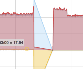
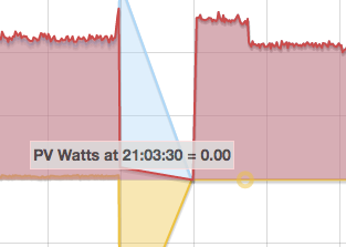
Did you apply the a.c. power at the same time as, or before, the 5 V? If not, it thinks there is no a.c. adapter and it is on battery power.
When that happens, it cannot detect the direction of power flow, and so sees the ‘keep alive’ power consumed by your inverter as production.
The LED tells you: It is on for 10 s, then the LED flashes ONCE if no a.c. adapter is detected, or 10 times with a.c. present.