Have you looked at the “Learn” section. The full details are there, along with links to all the sketches ever posted.
Unfortunately, the attachments became “detached” when the old forum was archived. This is under discussion privately between the moderators and the site admins. Hopefully, there will be a means to recover the information. (We believe everything still exists, the linkage is the problem.) This thread has already been mentioned in that discussion.
It’s not hard to change the I/O details to match the emonTx V3.2, and from memory that’s all that is needed to convert Robin’s original sketches.
So notwithstanding the lost attachment, I’d choose the most appropriate sketch - possibly the latest - of Robin’s and convert it for the V3.2.
I have Robin Emley’s PV Router (Very excellent it is too at doing what it does) and am waiting for the CM software to come out of Beta to implement a separate system to log various feeds including routed and exported energy - it being a bit of a pain to log data manually. However, now I wonder rather than 2 discrete components (largely replicating 50% of already implemented measurement and display), maybe this could all be implemented within just the emonTX?
I am a newbie, so not well versed in coding for the Arduino, in the article above it was talked about converting Robins Sketch, but in this case I would like to keep both sketch’s functionality…
I know the hardware has improved/other faster chipsets available, how much overhead and i/o is available in order to implement both systems within 1 unit?
If I was logging the routed power, I wouldn’t need to display on the unit the amount of energy routed, thus freeing up o/p’s currently used to display this energy. I also have one of your old displays that I would like to tie into the system i.e. use the internal RFM to communicate to the display, and an ESP8266 WiFi unit to connect into the network. Not interested necessarily in any temp measurements, but might investigate using one to turn on a tank stirrer (external pump) to maximise energy storage and reduce time to get hot water to taps at a later date.
Although the CM code is based on Robin’s, and it should be easy enough to put the diversion code back in, then depending on exactly what you want to log, it might be easier to add the code to send the reports to whichever sketch of Robin’s that you’re using. Have you looked at all of Robin’s published sketches, they are on his www.mk2pvrouter.co.uk website.
But, as you say you are “not well versed in coding for the Arduino”, I’d be sorely tempted to keep it as two separate units.
The emonGLCD?
That’s not true in this case - both Robin’s hardware and the emonTx use the same processor. If you can’t squeeze enough performance out of the Atmel '328P, you’d need to move away from that completely. (See the various STM 32 threads - but we’re a long way from a fully working version of that, both hardware and software-wise.)
I was just going to edit my post as I had realised I had got the name wrong! Sorry Robin. However when I tried it just said Abandon or Keep…
So the CM software is loosely based on Robin’s… so if the diversion code was added, I would probably strip out the part of the sketch that displays diverted kWh locally, which would free up most of the I/O, and as I said previously use a ESP8266 to log the data to CMS, this I guess keeps most of the code as is apart from the diversion code. I did look at robins published sketches 6 months ago when I built the router. Just had a look again and it seems that there are a lot more sketches added, including data logging via RFM… and possibly in OEM format. Does this mean that if I use the correct sketch I could possibly log my data into a emonBase?
Ok so now i’m even more confused as to the direction I should take. Basically I really don’t want to replicate what I’m doing already if I don’t have to - there is a finite amount of CT’s I can get into my CU! and 2 CT’s on the same live conductor or adjacent to each other might not be a good idea.
I guess I need to dive into the code of both and see what I need to do… any pointers here would be greatly appreciated. I did much coding when I was younger, but mostly machine code on x86 systems at college, but that was in excess of 20 years ago probably more like 30! I’ve got some self teach packages based on Arduino and other’s but it will be a deep learning curve…
And, yes the emonGLCD, couldn’t remember the name of it! Can this still be used to display the data collected by emonTX via the RFM? I believe I will have to change the RFM I have already.
When you say ‘(See the various STM 32 threads - but we’re a long way from a fully working version of that, both hardware and software-wise.)’ do you mean there is still plenty of available overhead available with the 'Atmel ‘328P’ i.e not necessary, or that the change to other processors hasn’t been completed yet?
A history lesson:
Robin developed his “CM” code for his router/diverter using the Atmel 328P processor - the same as the emonTx uses. OEM asked him to supply them with a plain measurement derivative, which they converted to a library, adding reporting of currents. Unfortunately, they didn’t realise that to save on processing, Robin had only fully removed the d.c. offset in the voltage channel, because he only needed power for calculating the diversion. The result was the current measurements were way out as they contained a false d.c. component. I realised the problem (having worked with Robin in the early days of his router) and corrected the problem. In doing so, I realised that there was a lot of unnecessary processing going on, so I simplified the algorithms and freed up a significant chunk of processor use. That’s more or less the present state of the CM library.
So without setting everything up again and doing more measurements (and probably adding back in the diversion code) I think - but I don’t know - that the CM library could be converted back to a diverter relatively easily. But I don’t think I’d go that route.
What I suggest is you take one of Robin’s sketches - probably Mk2_RFdatalog_5a.ino - and look at that. I’ve had a very cursory look at it and I don’t see a problem with using that with your GLCD (one or both might need a minor tweak).
The ESP8266 uses the serial output - the same as used by the programmer - so no need to change any hardware there, but the data that the sketch sends as it stands is not in the format the ESP8266 expects, so that will definitely need reformatting. But that’s only exactly that - change the formatting. So more of an irritant and not a major problem.
No, there isn’t plenty of processing power left in the '328P, the CM and 3-phase sketches push it pretty close to the limit, to the extent that handling the RFM69CW in RFM12B compatibility mode is a problem. And yes, we’ve been looking at the STM32 (the development board works for monitoring with a slightly modified emonTx Shield) but development seems to have stalled.
Why? unless you have different frequencies, probably not. What do you have at present?
(There’s a page in “Learn” to help you identify the modules if you’re unsure.)
OK I have a RFM12B 868MHz one in my emonGLCD - actually its not in it as I left it out - Glyn had said you had standardised on 433MHz in a request I had raised at the end of March this year, and didn’t stock them any more.
Do you have anything else on 868MHz? Those aren’t stocked because few people ordered that frequency, but they are available elsewhere.
If you have nothing (or Robin’s is 433 MHz), then I’d go with that unless 433 MHz is heavily used where you are (for doorbells, baby alarms, garage door openers etc).
No none of the above, so just need matching units of the same freq. Also I note you didn’t mention the option of interfacing the PV router into a EmonBase instead… I’m not precious about keeping local display on unit as long as it’s logged elsewhere…
If the data is broadcast, then the emonBase can be configured to receive it and do whatever you want thereafter with it (including save it and display web pages, etc).
But you didn’t actually say where your CMS might be…
(N.B. The CM library was released a while ago, it’s now on V2.02, having had some functions added.)
I was talking EmonCMS… Although I have a Server (HP ProLiant MicroServer N54L - on 24/7) which is used as a Video/Audio server and Storage for Security Camera’s, so I could store the data locally…
I presume you can use the HP server to host emonCMS, or you can use the pre-built image on a RPi.
The options to get the data from your Mk2 to the server are wired or radio. If you go for wired, I think you can use the programmer connection on your Mk2 to send serial data to an ESP8266, thence by Ethernet to your server.
If you choose radio, then as well as sending to your emonGLCD, you can receive the data with a RFM69Pi board attached to a RPi (aka emonBase). You can stop there and run emonCMS on that only, or from that use a wired Ethernet connection to the server, you could indeed use both (and have two instances of emonCMS, one on each of the two machines, each backing up the other).
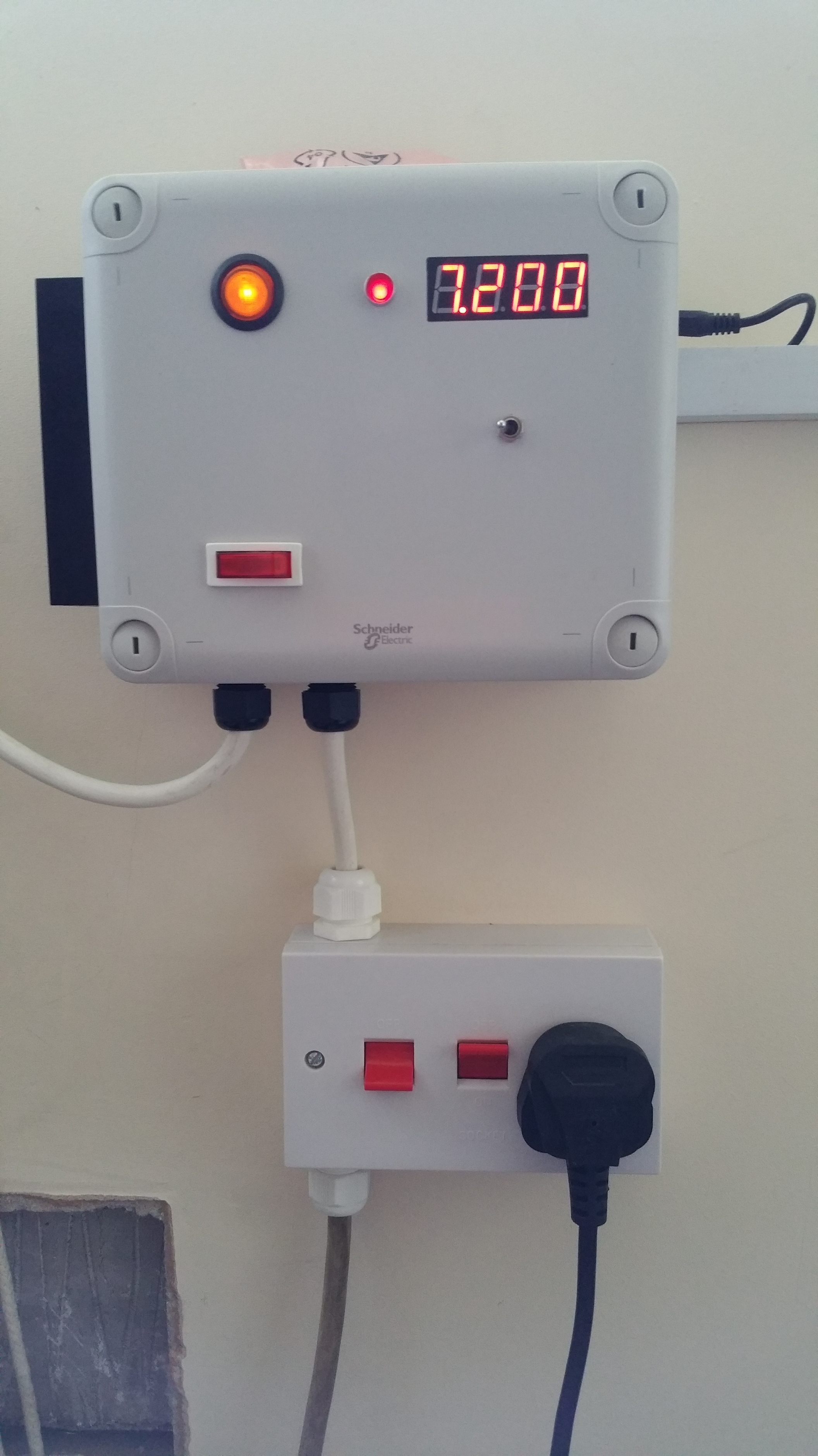
I did reuse the sketch mentioned at the top. I’m using an SSR from rs components (https://uk.rs-online.com/web/p/solid-state-relays/3582892/) as I wanted to avoid counterfeit SSRs which seem to be a problem. I had to change the pinouts at the top of the code as mentioned. I then run a long ethernet lead up to the airing cupboard to connect the SSR, I used a left over heatsink I had spare but I’m unsure if its big enough and need to finish putting it neatly into a project box.
Sadly, I think my meter is incompatible with the burst method used as even with the code in normal mode my electric meter (Secure Liberty 100) still shows import being counted. In hindsight why did I bother fitting a smart meter! Luckily Robin put a function in to allow a certain amount of export before diverting, so I’ve currently just added a 100watts here.
If you can find a similar heatsink advertised along with its thermal resistance (°C/W), then knowing the dissipation of the triac (near enough 15 W @ 15 A rms) you can calculate the case (mounting tab) temperature of the triac, hence the junction temperature because the thermal resistance junction to case is 0.6 °C/W. The maximum junction temperature is 125 °C.
It’s for situations like that where you need a “class D” (high frequency PWM) switch, rather than a burst-mode triac. I say that because filtering the high frequency noise is easier than for a phase-controlled unit.
Thanks Robert, I’ll look into calculating the heatsink size properly. I may just have to stick with diverting some power away as a buffer.
Any recommendations on “class D” switches? The learn pages state nobody has built a DIY one but at least one commercial one is available, although it doesn’t state what that commercial one is.
I believe G&T both have Eddi units, but I could be wrong.
I think one manufacturer did claim a patent on the use of PWM for the purpose, but as the principle has been in the public domain for many decades - I remember the venerable “Wireless World” publishing a design for a PWM class ‘D’ audio amplifier, but don’t ask me to quote chapter & verse - that could be challenged, as I’d contend that its extension to power control would be “obvious to a practitioner of the art”.