Hey Guys,
I’ve been messing around with my Emon TX Shield and I am out of ideas what’s wrong.
The voltage readings of my AC/AC PSU divert to 0 after a few readings, even though I calibrated everything according to the manual.
My gear:
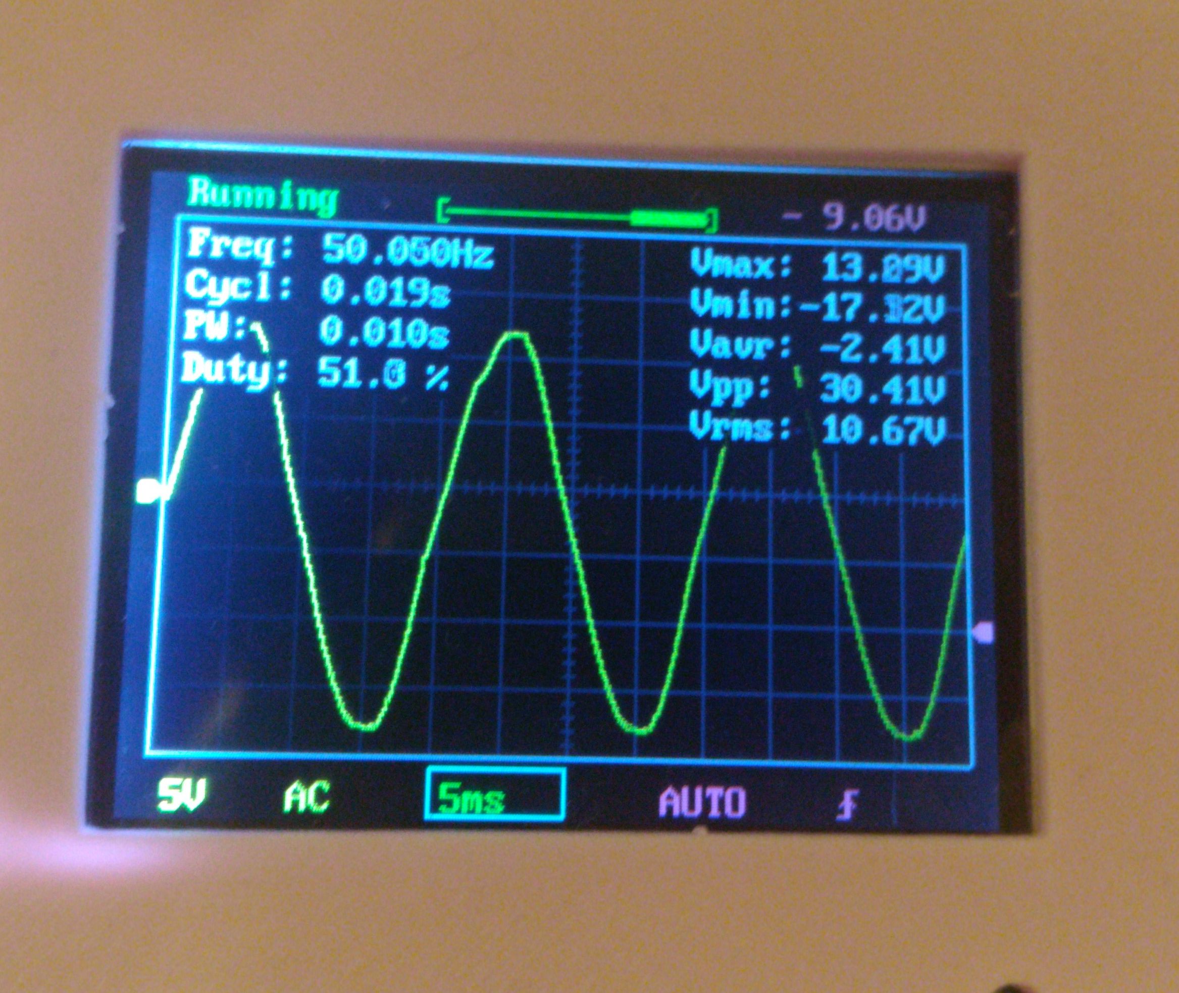
- No-Name AC-AC Adapter with 10.5Vrms (Says its 9V) and 600mA. A nice sine wave according to my oszilloscope.
- Emon TX V2.5, Arduino Uno over Serial for debugging, powered over the AC/AC-Adapter with a diode and a 4700uF Capacitor to smooth out the sinewaves.
What I did:
- Measured the resistors of the TX Shield for the Probes, they gave readings of 25 Ohms ± 0,1 (But they say 330 on them… strange?!). Calculated calibration factor (100A/0,05A / 25 Ohms); shoud be 78.43.
- Measured Mains with two Multimeters: 229,5V (totally ok for Germany, we should have 230V)
- Loaded up the Sketch without the AC/AC Plug use, took a 2000W heater and adjusted the Calibration factor until Serial output said, that the heater had the same reading as the wallplug-powermeter. → Real calibration factor is 69.230 (no wonder, the resistors are 25 Ohms instead of 33)
- Loaded up the Sketch with the AC/AC Plug-feature and went on with the EU-Plug startpoint of 260.0 for voltage calibration.
However, the values decrease to 0V after the first reading and stay there. If I leave out the real power calculations, the values given for my 3 CT probes make somewhat sense.
What happened here? and what can I do to get actual readings?
I tried punching in wild numbers for voltage calibration, all divert to 0. I also looked again at the AC/AC adaptor with my oszi. All fine.
Redid all soldering points for the AC/AC adaptor connection.
And everything is working fine with the no-voltage sketch…
Serial output: My calibration:
emonTX Shield CT123 Voltage example
OpenEnergyMonitor.org
Node: 6 Freq: 433Mhz Network: 210
11 5 23 222.96
0 0 0 1.82
0 0 0 0.04
Complete Github Stock Sketch:
emonTX Shield CT123 Voltage example
OpenEnergyMonitor.org
Node: 6 Freq: 433Mhz Network: 210
14 5 21 222.00
0 0 0 1.83
0 0 0 0.04 (and so on for hours)
No real power calculation calibrated sketch:
emonTX Shield CT123 example
OpenEnergyMonitor.org
Node: 6 Freq: 433Mhz Network: 210
43 46 373
36 31 379 (and so on for days)
