Emontx-shield as solar diverter

Hi all,

I was wondering if someone could point me in the right direction. I have been planning to build a solar diverter for a while now in replacement to my old one.

I have a emontx shield and arduino Uno ready to go. Has anyone done this before? Be an interesting little project.

Question is where would I connect the 3.3V to my SSR for the switching of the immersion heater. The spare terminals appear to be for the DS18B20 sensor.

https://learn.openenergymonitor.org/pv-diversion/mk2/build

Any advice or pointer would be much appreciated.

Thanks

Gareth

Have you looked at the whole section in Learn?

Robin’s Mk2PVRouter started off as an Arduino build, so there’s a lot of information here or on his website (www.Mk2PVRouter.co.uk) that with very little change should get you going.

Both MartinR’s and Robin’s sketches should work with very little change, probably only I/O pin changes.

If you’re using a commercial SSR, first a warning to make sure you have a genuine reputable brand and not a counterfeit one, because there were reports of units bought cheaply that failed quickly or overheated. The second thing you want to watch out for is the input voltage required by your SSR. If you’re using an Arduino, the 5 V logic output on the Arduino’s IO Pins - that’s where you drive the SSR, not from the Shield itself - should be OK for most SSRs.

if you want you can try my version of diversion it works with uno or wemosR3 (uno/wif)-- I used mine for years with out issue …

here a today graph from cooking Easter dinner

if using Cheaper fortek buy one double the rated as the cheaper ones rate there at the amperage they burn at. as that how most chinese stuff is rated the fail volt or amperage

Hi,

Thanks for your reply.

I purchase a SSR from RS and cost around £30 so hopefully I have removed the risk of any cheap/Chinese duplicates.

Yes I have had a good read through the learning material. I’m am trying to figure out which digital output I need to use for switching my SSR. The emontx v3 uses DI3. But as I am using the emontx shield that one is already in use. Im am thinking DI7. Could someone confirm this please?

Thanks @stephen I have a few spare node mcu’s banging around. What items did you use for the CT and Voltage measurments?

Cheers

Gareth

I use the txsheild as well - my diverter is cascading so I use 9,10 and 3 on uno as then I can use pwm.h to adjust to frequency I like… but not knowing what else you are all driving with your uno - the basic empty txshield only uses A0 -A4 all the rest are free to use

i use the wemos R3 which is a combination uno and esp that way i can send info to and from the my diverter

Thanks for that. I will give it a go this week.

I like the idea of using the esp chip but ive already solders the RF chip to the shield. Will your sketch work this the RFM69CW?

I do like the idea of being able to enable/disable the solar diverter. I current use a sonoff relay to switch the 230Vac on and off for my current diverter. I would prefer to do this on the uno control side instead of the 230V power side.

As you can see my current diverter exceeds the solar generated line. My ESS uses PWM to charge my powerwall. It perfectly follows my solar generated line. I want to get the Solar diverter to do the same if I can.

Cheers

Gareth

not likely with out alot of modifications – what pins do you use with the RFM69CW if 9 and 10 are free then you can still use pwm.h which makes it more accurate

Best to have a look at the schematic.

To bet honest if it can work as a stand alone device for now I can easily switch the 230Vac and control it via my Home Assistant Automation. I would be happy with that.

Im using a emontx for my logging so I bought the shield for a bit of play time :slight_smile:

yeah it would work and designed to work as a standalone device. it was standalone device for a long time . then I connected an esp to it to send data as daughter board , and the final version that I use now is with the wemosR3 as everything is built in and it eliminated the need for a second power supply for the esp - i could power it from one powersupply but was unstable and prone to stalling - currently with the use of the wemosR3 it has not stalled once in the last year of use – my diverter works best if cascading smaller elements but will work fine if only one larger element just not as accurate if compared to using multiple smaller ones

Hi All,

Been having a play with getting my Uno and Emontx Shield working as a solar diverter. I have chosen to use a decent quatility SSR suitable for 280Vac and 25A. I have downloaded Mk2i_PV_Router_rev4b.ino that @calypso_rae wrote and uploaed using IDE.

So far I have amended the sketch as my voltage pin is 0 on the sheild. CT1 is pin 1. For now I do not feel I need to amend anymore. This is my set up below for illistration.

I ran the MinAndMaxValues.ino and RawSamplesTool.ino got these values. This was with a 2.5kw load switch on half way through to confirm the ADC values changed.

TBH i dont know if these are correct values. The diff is 80 with a 2500W load?

When I switch the slow cooker on to simulate a 100-350W PV generation, my SSR switches on and stays on. So in the sketch pin 3 which is my SSR states.

digitalWrite (outputPinForTrigger, HIGH); // the external trigger is active low

Does this mean that when there is NO surplus solar the output pin will be at 5V? Because that seems worng. Surely it should be 5V to operate the SSR when there is surplus.

Also I do not understand this line in the sketch. Could anyone explain this one please?

boolean runTimeSelectionOfAFstatusIsEnabled = true;

Finally I have tried changing the direction on the CT to but that didnt change anything.

Any help would be much appreciated. Maybe to one you its blinding obvious why I cannot get my set up to divert to the kettle.

Cheers

Gareth

AF refers to anti-flicker mode. This is explained to some extent in the comments at the top of the sketch.

That is indeed the case. If you look at the circuit diagram of the trigger on page 8 of the ‘Learn’ section, you’ll see that the opto-trigger i.c. is wired between the 3.3 V rail and the output, so it is active low.

You can easily edit the sketch to change that. That will certainly prevent correct operation until you change it. That is easily done: all you need to do is swap the order of TRIAC_ON and TRIAC_OFF in

enum triacStates {TRIAC_ON, TRIAC_OFF}; // the external trigger device is active low

You should probably also change this earlier line just after the pin mode is set:

digitalWrite (outputPinForTrigger, HIGH); // the external trigger is active low

from HIGH to TRIAC_OFF.

The other point about the blindingly obvious is your main c.t. must be downstream of the actual feed to the slow cooker because you’re passing the slow cooker feed backwards through the c.t., so that it sees the reverse power of the PV infeed and not the true power to the slow cooker. (It’s hard to express in words.)

Do you know the value of the burden resistor for your CT? The small range of ADC values with your 2.5 kW load suggests that a very low burden value may be in use. For this application, I would recommend a value around 120 ohms. The working range of that measurement channel only needs to be sufficient to cater for your PV and the Mk2’s dump-load, not your whole house consumption.

When simulating surplus power to test your “Mk2” diverter, you will need to use a test rig something like this:

Note that the CT has to pass around two cables where current flows in opposite directions. This is so the controller can adjust the load’s consumption to match the synthesized PV generation.

Hi,

Thank you for your replies. I made the amendments to the sketch but unfortunately this does not work still. I think my first issue is the calibration issues and probably caused by the hardware -CT burden resistor.

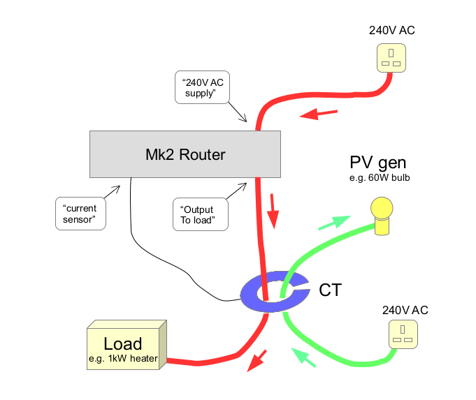
The CT burden resistor on the Emontx sheild is 33ohms. I think like you said I need to replace this with a 120ohm resistor so it uses a larger range on the ADC.

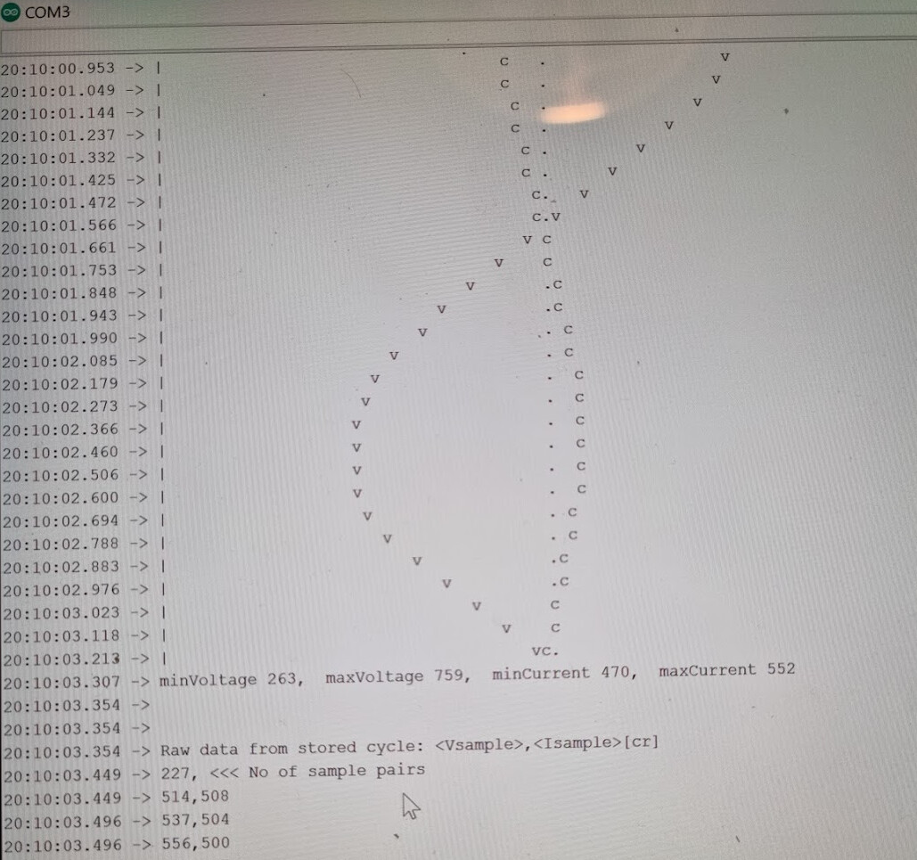
I will change this resistor and re-run the sketch. Just so I calibrate these system correctly. If I leave the default vales in for now. Could you explain what these values should read when running Tally mode please? See below is the results of running Tally mode for 10secs. Min load is 0W and Max load set to 200W. Whilst running this sketch I used a 150W load.

20:02:15.458 → -------------------------------------
20:02:15.504 → Sketch ID: Mk2i_PV_Router_rev4.ino
20:02:15.551 → ADC mode: 125uS fixed timer
20:02:15.598 → Output mode: normal
20:02:15.598 → Auto-select?: yes
20:02:15.644 → Extra Features: TALLYMODE
20:02:15.644 → powerCal = 0.0610
20:02:15.690 → phaseCal = 1.00
20:02:15.690 → >>free RAM = 681
20:02:15.736 → capacityOfEnergyBucket_long = 2950819
20:02:15.782 → lowerEnergyThreshold_long = 1475409
20:02:15.829 → upperEnergyThreshold_long = 1475409
20:02:15.875 → minCycleCountsBetweenActivations = 0
20:02:15.921 → >>free RAM = 671
20:02:15.921 → ----
20:02:15.921 →
20:02:15.921 → Tallymode setup:
20:02:15.968 → Time to run (secs)? 10
20:02:19.009 → Min value (Watts)? 0
20:02:21.400 → Max value (Watts)? 200
20:02:26.492 → Recording will start in 3 seconds …
20:02:39.550 → Results for this run:
20:02:39.550 → 0, ← min value of tally range (W)
20:02:39.596 → 200, ← max value of tally range (W)
20:02:39.643 → 2.00, ← step value between tallies (W)
20:02:39.691 → 100, ← No. of tallies
20:02:39.691 → 10, ← duration (secs)
20:02:39.738 → 500, ← no of values tallied
20:02:39.786 → 80, ← loops per mains cycle (av)
20:02:39.786 → ***
20:02:39.786 → >200W, 0
20:02:39.834 → 199W, 0
20:02:39.834 → 197W, 0
20:02:39.834 → 195W, 0
20:02:39.834 → 193W, 0
20:02:39.834 → 191W, 0
20:02:39.881 → 189W, 0
20:02:39.881 → 187W, 0
20:02:39.881 → 185W, 0
20:02:39.881 → 183W, 0
20:02:39.881 → 181W, 0
20:02:39.928 → 179W, 0
20:02:39.928 → 177W, 0
20:02:39.928 → 175W, 0
20:02:39.928 → 173W, 0
20:02:39.928 → 171W, 0
20:02:39.982 → 169W, 0
20:02:39.982 → 167W, 0
20:02:39.982 → 165W, 0
20:02:39.982 → 163W, 0
20:02:39.982 → 161W, 0
20:02:39.982 → 159W, 0
20:02:40.039 → 157W, 0
20:02:40.039 → 155W, 0
20:02:40.039 → 153W, 0
20:02:40.039 → 151W, 0
20:02:40.039 → 149W, 0
20:02:40.039 → 147W, 0
20:02:40.100 → 145W, 0
20:02:40.100 → 143W, 0
20:02:40.100 → 141W, 0
20:02:40.100 → 139W, 0
20:02:40.100 → 137W, 0
20:02:40.100 → 135W, 0
20:02:40.154 → 133W, 0
20:02:40.154 → 131W, 0
20:02:40.154 → 129W, 0
20:02:40.154 → 127W, 0
20:02:40.154 → 125W, 0
20:02:40.154 → 123W, 0
20:02:40.194 → 121W, 0
20:02:40.194 → 119W, 0
20:02:40.194 → 117W, 0
20:02:40.194 → 115W, 0
20:02:40.265 → 113W, 0
20:02:40.265 → 111W, 0
20:02:40.265 → 109W, 0
20:02:40.265 → 107W, 0
20:02:40.265 → 105W, 0
20:02:40.265 → 103W, 0
20:02:40.265 → 101W, 0
20:02:40.265 → 99W, 0
20:02:40.311 → 97W, 0
20:02:40.311 → 95W, 0
20:02:40.311 → 93W, 0
20:02:40.311 → 91W, 0
20:02:40.311 → 89W, 0
20:02:40.384 → 87W, 0
20:02:40.384 → 85W, 0
20:02:40.384 → 83W, 0
20:02:40.384 → 81W, 0
20:02:40.384 → 79W, 0
20:02:40.384 → 77W, 0
20:02:40.384 → 75W, 0
20:02:40.384 → 73W, 0
20:02:40.384 → 71W, 0
20:02:40.424 → 69W, 0
20:02:40.424 → 67W, 0
20:02:40.424 → 65W, 0
20:02:40.424 → 63W, 0
20:02:40.424 → 61W, 0
20:02:40.491 → 59W, 0
20:02:40.491 → 57W, 0
20:02:40.491 → 55W, 0
20:02:40.491 → 53W, 0
20:02:40.491 → 51W, 0
20:02:40.491 → 49W, 0
20:02:40.491 → 47W, 0
20:02:40.491 → 45W, 0
20:02:40.528 → 43W, 0
20:02:40.528 → 41W, 0
20:02:40.528 → 39W, 0
20:02:40.528 → 37W, 0
20:02:40.602 → 35W, 0
20:02:40.602 → 33W, 0
20:02:40.602 → 31W, 0
20:02:40.602 → 29W, 0
20:02:40.602 → 27W, 0
20:02:40.602 → 25W, 498
20:02:40.602 → 23W, 2
20:02:40.602 → 21W, 0
20:02:40.602 → 19W, 0
20:02:40.643 → 17W, 0
20:02:40.643 → 15W, 0
20:02:40.643 → 13W, 0
20:02:40.643 → 11W, 0
20:02:40.643 → 9W, 0
20:02:40.712 → 7W, 0
20:02:40.712 → 5W, 0
20:02:40.712 → 3W, 0
20:02:40.712 → 1W, 0
20:02:40.712 → <0W, 0

Does this mean my sketch reads this as a 25W load and the ADC value is 498?

Thanks for your help :slight_smile:

Cheers

Gareth

I was hoping Robin would come back and explain Tallymode, it’s not a feature that I’m familiar with, though there is a description in the comments at the top of the sketch.

If I’m reading the notes correctly:

yes, but

No, it hit the 25 W value 498 times in the 10 s that Tallymode ran for, so either your mains was a bit slow or the timing not spot on. And there’s no switching taking place.

But are you aware of the general principle of the diverter? Because it should work - in some sort of way but not ideally - irrespective of calibration, because it depends on detecting zero nett power flow. Export (positive power) raises the level in the “energy bucket”, while import (negative power) lowers the level. When export (the level in the ‘bucket’) reaches an upper threshold, the dump load is turned on and remains on until the level reaches the lower threshold, when it turns off. Everything else - AF mode, the burden value, the CT rating, the calibration itself, all affect how it works, but shouldn’t stop it working. Only a fault or a mistake in the edits to the sketch, or the orientation of the c.t., could do that. And the fact that Tallymode is giving power readings removes the most of the possibility that the sketch is wrong.

As an initial test, and if you haven’t done so already, I’d write a “one-line” sketch to turn the dump load on and off, to check that your SSR is working. Ideally, incorporate Robin’s enum triacStates {TRIAC_ON, TRIAC_OFF}; (which you should have changed around) and check that TRIAC_ON & TRIAC_OFF do the correct things with your SSR.

Next, I’d make up the test rig that Robin suggests above, but don’t run the dump load wire through the c.t. Start the sketch, turn on the “P.V”, and see if the dump load turns on after a while. If it doesn’t, turn the c.t. around, restart the sketch and try again. That should establish that the ‘energy bucket’ is filling and reaching the upper threshold. When it does, without stopping the sketch, reverse the c.t. on the wire (it’s quite safe to do this) and the dump load should turn off when the bottom threshold is reached.
If that’s OK, put the c.t. back as it was immediately before this and put the dump load cable through the c.t. as well, and you should see the load turn on and off according to the amount of P.V. You can double or triple the P.V. by passing the wire two or three times through the c.t.

In normal mode, the two thresholds are set to the same value - half-way up the “energy bucket”. In AF mode, they separate to give more time in each of the ON or OFF states.

Hi Thank you for your reply @Robert.Wall.

Update on where I was with the my solar diverter project. I could never really get the control I wanted using the zero crossing relay with the emon shield. I was really tempted with buying and Eddie from Myenergi but they were quite pricey. All along I wanted to build my own that had the same control as the eddie. The objective was to get my diverter to perfectly track the solar generated (Same as my Energy Storage System). Unforunately I could not get this control with the Zero crossing relay. See below.

As I already have a EmonTx and all the power readings required for the control. I decided to build something a little different. I decided to go with a phase angle control relay driven by a PWM to 0-10V DAC. The PWM signal come from my emon base Rpi. Then wrote my own control loop in Node red to gain the control I wanted. See below a screen shot from a few days ago when it was nice a sunny.

Really happy with the results.

If a few people are interested in my build I am happy to share the box of tricks and the code I made with other people.

Cheers

Gareth

Glad to know you’ve got it working. A lot of people have had success with burst mode - using both commercial zero voltage Solid State Relays and of course Robin’s own diverter kit. If you want to bypass the Pi and the inherent delays in getting the data to it, he has a sketch to drive the phase control from an Arduino/emonTx (with a few adjustments given the emonTx isn’t designed with analogue outputs in mind).

Cheers.

Dont get me wrong I had success with the zero control relay. It worked. It did the job in divertering 100’s Kw’s to my immersion heater. But I could never get it to perfectly track the solar generation.

I did have to adjust the sketch update interval to a lower value in my emon tx gain the control I needed. Been running for 1 month now with no issues. Hopefully stays that way :slight_smile:

Cheers

Gareth

That’s the point of Robin’s sketches compared to the default emonTx sketch: his “faster control” sketch reacts to a change within 1½ mains cycles.

I had no issues with the reaction time. It was quick to react. But at low solar generation the control wasnt great IMO. The zero crossing relay I found was good at higher solar generation. See below.

Now al low solar generation the phase angle control relay works exactly as I want it to. See below. I live in the UK where the solar is never that great so low loads are quite common.

Cheers