Hi, I am running the emonTXv4 with wifi and have been trying to improve the signal strength. As the emonTX is outside and my router is approx. 30 feet inside the middle of my house, I was approaching this as a router issue and replaced the router antenna with a 12dB high gain antenna with a low loss cable. This improved things a bit, but it is still sitting around -80dB at the emonTX.
My next step was to use an external antenna on the emonTX that I could try placing in different spots. This is when it got interesting.
It made no difference if the antenna was attached to the emonTx or if the emonTX had no antenna attached. This made me think there was a connection issue on the emonTX board. I took the board out of the emonTX and all looks good.
Next, I took the emonTX inside the house and powered it up beside the router - 3 feet away. The emonTX has a signal of -65 to -72 with the antenna attached and around the same with the antenna removed. This close to the router I should be seeing values around -30.
So, is there a setting in the emonTX for adjusting wifi? It almost seems like the antenna connection or the wifi board is not connecting properly. I have 5 emonTXv4s and they all exhibit similar behavior.
Not sure what to do to improve signal quality - any assistance is greatly appreciated.
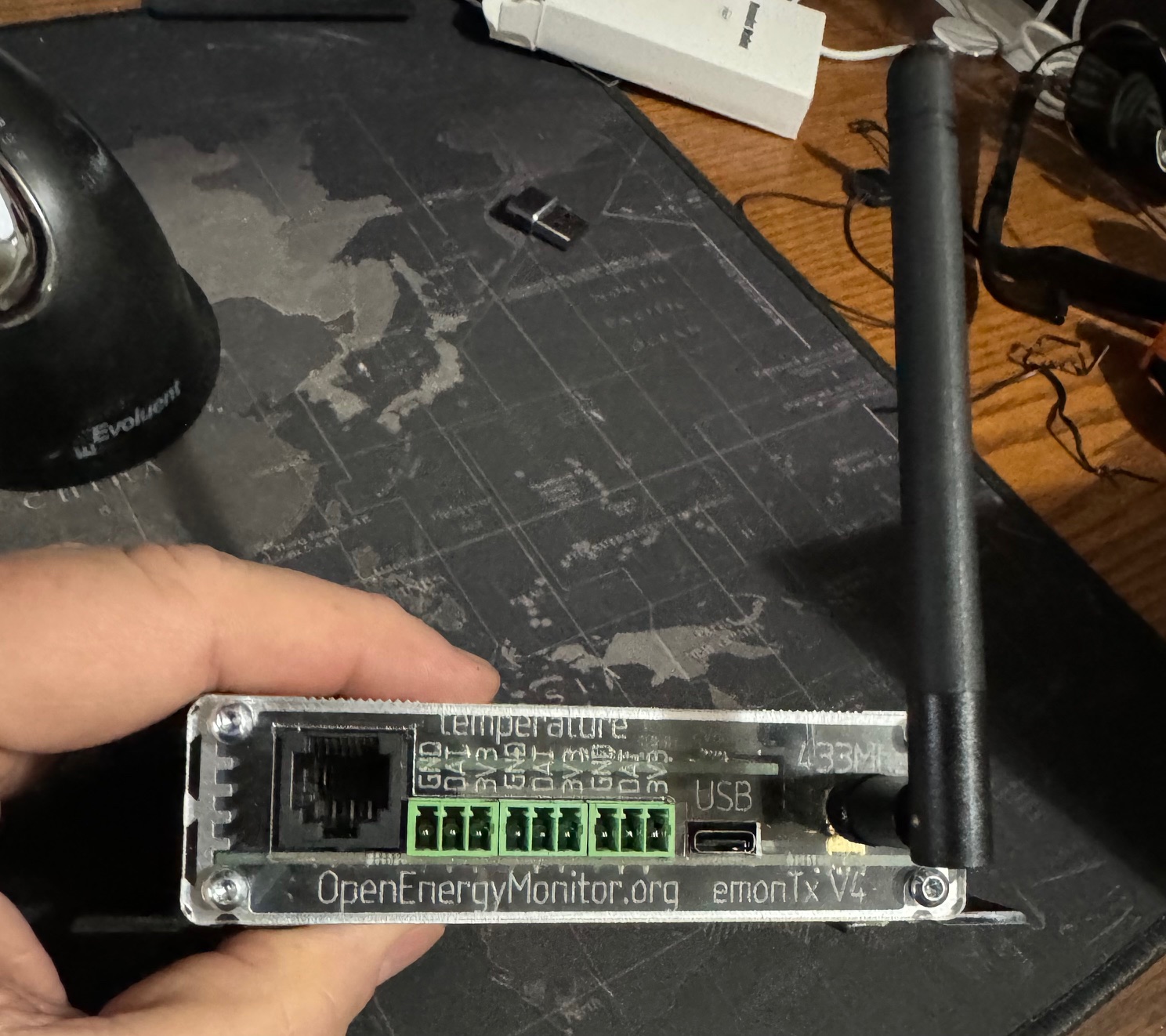
Would you, by any chance, be talking about the UHF ISM band antenna - the one that plugs into the SMA connector that comes out next to the USB-C connector? Because if you are, that isn’t Wi-Fi.
The Wi-Fi antenna is inside, part of the Wi-Fi module (probably a Huzzah ESP8266) that sits on the main p.c.b. (and not to be confused with the UHF RFM69CW module that’s soldered on the main p.c.b. immediately behind the SMA connector Or that’s my understanding. I don’t have the Wi-Fi version, so I can’t be definitive.
You might damage the RFM69CW UHF radio if you operate it at full power (not the default) without an antenna.
Like it says on the panel immediately above it - it is for the 433 MHz (that’s UHF) ISM (Industrial, Scientific & Medical) band radio. Once again IT IS NOT Wi-Fi.
Why have it? - for everyone else who uses the built-in radio to send to the emonBase rather than Wi-Fi.
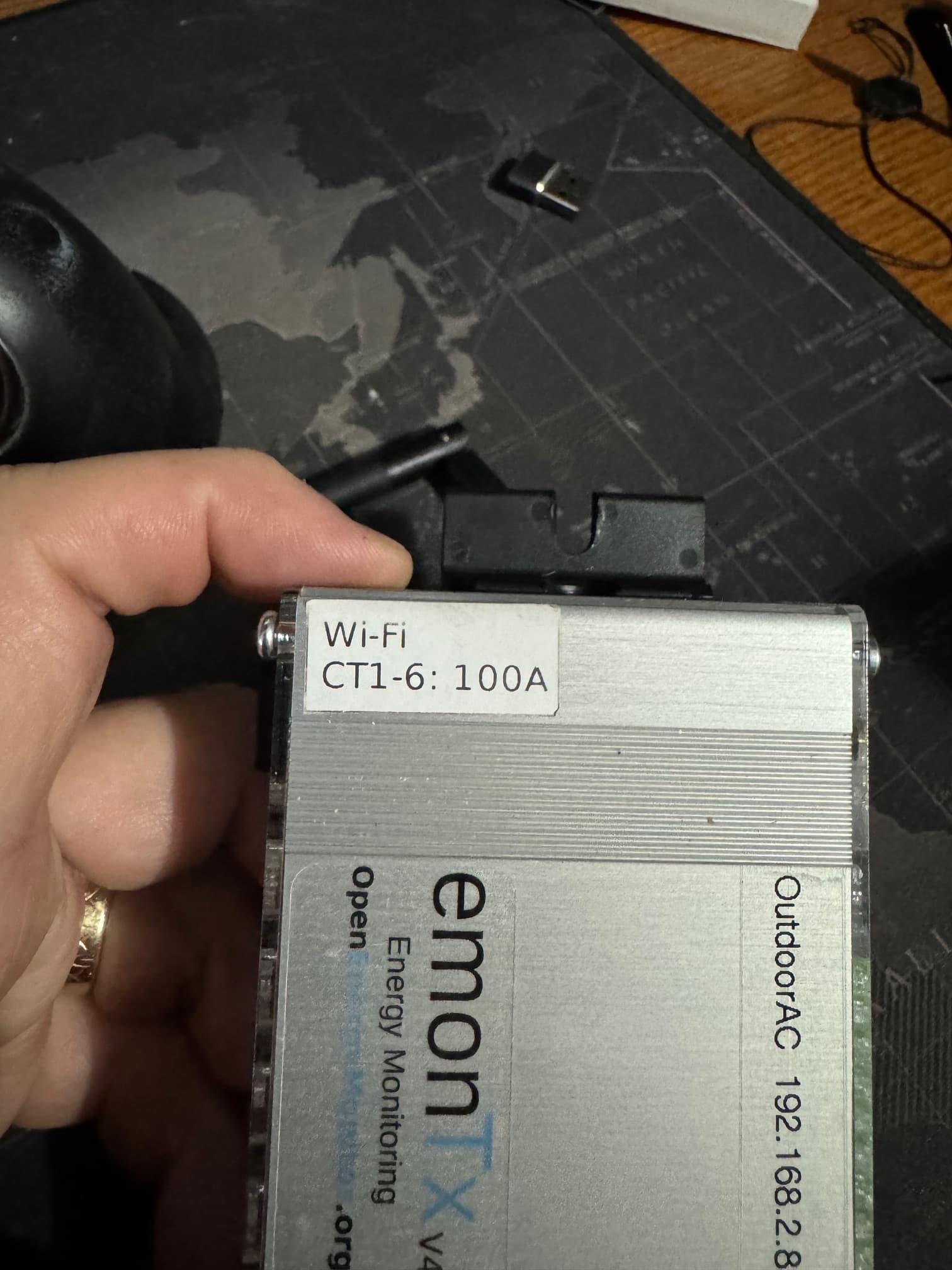
Look back at my previous post and read the second paragraph again. Then look at your second picture. The piggy-back circuit board you can see edge-on behind the ‘N’ of GND, the ‘A’ of DAT along to ‘US’ of USB is the Wi-Fi module, and the Wi-Fi antenna is part of this.
Robert,
thank you for the quick reply. The source of my confusion is the black rubber antenna that is included with the emonTXv4 WIFI kit. If the wifi module has a built-in antenna and the sma connector is only for the 433mhz band, then I am confused as to why the external antenna is included with the kit. This caused me to believe that the plexi glass labeling wasn’t changed for wifi and the connector would be used for wifi.
There is no documentation to say one or the other. @glyn.hudson can you clarify?
I answered that at least in part: if you operate the RFM69CW (this is the 433 MHz) radio at full power (which is not the default, the default is, IIRC, 6 dB lower) it will destroy the radio. Most users don’t have the Wi-Fi option and use the in-built radio instead. It’s standard with the emonTx4 (and the emonTx V3 which preceded it).
No, but then again I have been quite close to the design process.
Robert,
I appreciate your input and this is definitely helping to clear up my confusion. If I want to go away from using wifi, do I just remove the wifi radio and then connect to an emonBase (which I would need to order), or are there other components needed (such as different firmware)?
Looking at the “Wi-Fi” sketch - which is the one I assume you have, there appears to be a serious error in it (introduced when converting from my ‘demo’ sketch which accompanies emonLibDB) that will prevent it transmitting any data for the 6 basic power channels
Therefore, I think you’ll need to upload the “standard” sketch:
for clarification, are referring to preventing the transmission of data on WiFi or 433Mhz? I am assuming the latter as I do receive data via WiFi - but want to make sure I understand your reply.
Guess I need to read up on how to upload the standard sketch.
As I wrote, I don’t have any of the Wi-Fi expansion boards so I can only tell you what I know from looking at those pages and the published sketches.
When you remove the Wi-Fi board - whichever one it is - you are left with the ‘standard’ emonTx4, which can run either of two sketches.
One of these is the unmodified “demonstration” sketch which I published alongside the library emonLibDB, and this allows full use of the emonTx4 with the exception of temperature measurement, because that’s too slow and interferes with the high speed measurements necessary when you have (in your case) a split phase mains supply meaning two voltages and up to 12 currents to be measured. This does have the radio, but as yet no on-line configuration, it was only ever intended to show how to use the library.
[‘unmodified’ because in making this the “EmonTx4_DB_12CT_WiFi” sketch, the 433 MHz radio has been disabled - clearly accidentally - for power channels 1 - 6, and it will only work if you have the expansion board giving you channels 7 - 12.]
The other sketch is based on the old emonLibCM. This will only handle one voltage and 6 current measurements, but it will handle a few temperature measurements too - but adding these degrades the accuracy. It’s capable of ‘on-line’ configuration. It’s this sketch that I think you’ll need - but not if your emonVs monitors both legs of your mains voltage - for this you need emonLibDB.
Hi Robert,
thank you for the thorough explanation - I am continually impressed by this forum and how willing everyone is to help. This is greatly appreciated and is helping this old guy (me) learn a lot of new skills.
Blockquote This will only handle one voltage and 6 current measurements, but it will handle a few temperature measurements too - but adding these degrades the accuracy.
This is a bit concerning in my configuration. I am using the emonTX to monitor commercial HVAC units with CT clamps on compressors and fans (typically 3 CTs but up to 5) and two temperature probes for measuring return and conditioned air temperature levels. Is this only a concern with the default sketch for 433Mhz as I am not noticing any issues with accuracy currently?
If your present sketch is measuring temperatures, nothing will change.
I’m assuming you also have an emonVS to power your emonTx and provide the voltage sample for it to measure, are your HVAC units running on 120 V or 240 V?
Hi Robert,
We have both voltages. Most are at 208V, but split systems typically have compressors at 220 to 240 and the supply fan at 120. For split systems, I have 2 emonTXs (one for the 240V and one for 120V).
You do realise that the emonTx4, with the emonLibDB library and a 3-phase emonVs will handle both legs of your 120 - 0 - 120 V supply, but alas you’d need something else (an emonTx3 or 4, or emonTH) to handle the temperatures.
Thank you to everyone for all the help with the wifi issue I was running into. I did some more testing and wanted to share my findings as this may help in future product designs.
With the wifi antenna being on the wifi module and appearing on the underside of the module, signal strength is quite variable with the orientation of the emonTXv4.
On my router, I added a 12dbi high gain antenna with low loss cable to improve the signal from the router. This was based on a recommendation from an RF engineer colleague who does this for a living.
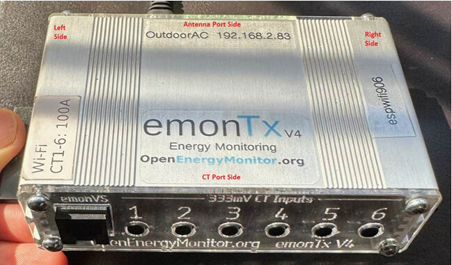
The test was conducted by placing the emonTX approx. 10 feet away from the router antenna (this was the length of my USB cable) at both the same height as the router antenna, and then on a stool 5 feet below the router antenna (all 10 feet away and clear line of sight). The picture below shows the various sides labeled to match the table below.
CT Port Side
Antenna Port Side
Left Side
Right Side
At same height as router antenna
-57db
-72db
-68db
-57db
Five Feet below the router antenna
-64db
-76db
-76db
-69db
So, you can see that the signal degrades if the emonTX is below the router antenna as it is then looking through the top of the emonTX enclosure.
I reran the tests with the entire board removed from the emonTX enclosure, and signal strength improved by roughly 5 dB.
A suggestion for future designs is to have an external wifi antenna port if possible and perhaps a non-metallic enclosure as an option.