Hi!
I’ve bought an emonTX with 4x 20 A CT clamps, to measure a couple of energy hoggers (PHEV, heat pump for a small plunge pool etc).
Since I already have a server running for other stuff, I installed emoncms on that, and hooked up emonTX to an esp8266.
All connections work work just fine and I get data into emoncms… But… The readings seem way off. The car charges with 1200 W according to emon, which should be impossible due to time it takes to charge, and the size on the battery. 2300-2400 W would be reasonable.
The heat pump should draw around 700 W, but only 200-250 W is reported.
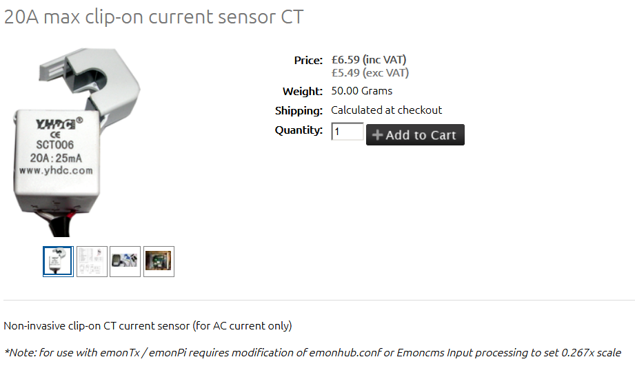
I’ve added x0.267 in emoncms according to the web shop for the 20 A clamps.
I’m using the AC/AC for voltage calibration, although it reports about 250 V, when around 230 V, or slightly higher, is expected.
Exactly what are those? And what is your electricity supply, single phase at 230 V L–N or 3 phases at 230 V L–N, or maybe even 3 phases 3 wires 230 V L–L?
The supply into my house is 3 phases at 230 V each (L-N), but the devices I’m trying to measure are single phased, so naturally they are only supplied with a single phase.
Unfortunately, those c.t’s are only good for 20 A on a 60 Hz supply and with a 5 Ω burden. You can read my test report in the ‘Learn’ section here. When used with the emonTx on a 50 Hz system, they are only good to about 15 A (~ 3 kW or a little more).
You main problem is that the current ratio is 20 A : 25 mA, therefore, with the 22 Ω burden fitted to channels 1–3 of the emonTx, the calibration constant should be 36.364. Unless you have changed it, the default value is 90.91, and that correlates with your low readings. You can change the calibration constant using the on-line interface (connect a serial monitor in place of your ESP, restart the sketch and you’ll see the calibration menu.
If you don’t want to do it that way, then the multiplier you need is 90.91 ÷ 36.36 = 2.5, not 0.267 (I’ve no idea where that value comes from.)
You are presumably using the EU plug version 77DE-06-09-MI. The output voltage of that is slightly different to the UK version that the calibration is set for, it’s 11.5 V ±5% at 230 V in, so the voltage calibration constant should be 260, not 268.97. Changing that in the sketch is the correct place and will also correct the power measurement, changing it emonHub won’t directly correct the power (the sum is done inside the emonTx) so you need to incorporate that correction into the power calibration there as well.
Note of course the a.c. adapter and your c.t’s must all be on the same phase for your measurements to be correct (even when you’ve made that change).
Yes – but how - or rather why - is it that and how did it get there. I have not tracked it down yet. I can’t relate 0.267 to any applicable values (or ratio of values) that I can think of. The emonHub power multipliers have been 1.0 for all time (AFAIK).
The low readings I get are after I apply x0. 267.
If I apply x2.5 to the original values, they are way too high.
Regarding the AC/AC adaptor, you are saying I can only measure on one phase for each emonTX I buy? Suddenly this is becoming pretty expensive. Or is it possible to measure on more than one phase but with lower accuracy? I’m not talking about measuring 3 phase 400 V, but individual phases at 230 V.
I’m saying the emonTx has only one voltage input. I’m saying that, unless you specified otherwise, your emonTx will have come to you with the default UK single-phase software, and that won’t accurately measure the real power if the load and the a.c. adapter are on different phases.
I’m also saying now that there’s a 3-phase sketch that you can download and install instead that will give a close approximation to the real power on 3 phases. It doesn’t know the amplitude of the other two phases of course, because there’s only one voltage input available, but it phase locks to that and shifts it by the nominal 120° either way to use as the reference for the real power calculation on the other two phases. So when we describe it as “approximate”, the approximation is only in the voltage balance across the phases. It’ll also work on a 3-phase 3-wire system, treating one phase as the neutral and it becomes a two-phase system. In that configuration, it cannot know the individual phase powers, but the total 3-phase power is correct.
The single-phase sketch will measure, but won’t report without a small modification, the apparent power correctly but with the same accuracy limitation due to not measuring each phase voltage separately.
Having looked at the numbers until my brain got into a tangle, I plugged a SCT006 into an emonPi, put 0.4 as the multiplier in emonHub, and got close enough to the correct power (Close enough meaning I set the current with MI analogue meter, not a digital true rms multimeter).
Here are my numbers: 2 A, 6 turns primary winding, so effectively 12 A primary current, no a.c. adapter, therefore the emonPi will be using 240 V as the default and showing apparent power, and that is 2917 W. It should read 2880 - so 1.3% error and I’m not sure the “emon” part of the emonPi has the default calibration anyway.
(Note: this in effect is the same software as the emonTx.)
And all that begs the question: Where does 0.267 on the Shop page come from?
I’ve flagged this to Gwil, so hopefully the Shop page will be corrected.
Many thanks for all the support!
It all makes sense now, I just have to dig out my old FTDI cable (or should I use an rPi perhaps?).
One more question though, according to your report on the SCT006 in the Learn section, it doesn’t have an internal burden resistor, but a diode instead to limit the output voltage. Is it possible to leave them unplugged, but clamped to a lead drawing <800 W for a couple of hours while I tinker with the firmware? Or will I burn the clamp?
If possible I would like to avoid opening up my fusebox and removing the clamps every time I need to tinker, as the latches seem a bit flimsy.
No current transformer should be left open-circuit. OK, it does have an internal protection diode, it should be OK, but you’re relying solely on that. The c.t. is so small that you’re unlikely to come to serious harm if the diode fails, but it’s still not something I’d do if there was another way. Why not turn the circuit off, twist a bit of copper wire around the plug (tip & sleeve, the ring is not used) and then you can put the power on, knowing that two things have to fail before you risk trouble.
If you change the sketch to the 3-phase, you can recalibrate each channel and the voltage channel in the sketch, then you won’t need the 0.4 in emonHub because the correct values will come out of the emonTx. I suggest reading all the documentation and the notes inside the sketch first, so that you have an overall view of the procedure.
I have it all running now, thanks a lot! I will try to do a summary in a couple of days, perhaps more people will be interested in this. I also added a little function to the emonTX sketch to measure time between pulses on my meter, and calculate mean power between reports since I couldn’t get emoncms to output any meaningful values on its own.
That’s good to hear, thank you. I still have not found where that wrong number on the Shop page came from. It’s correct now.
You are not the first to have a 3-phase system successfully set up, there are many working 3-phase systems - principally in Continental Europe but also Australia, and no doubt elsewhere. Interest in 3-phase in the UK is of course limited because the great majority of homes, and indeed small businesses, have a single phase supply and that is what the OEM equipment was designed for. The OEM Labs have only a single-phase supply.
I think the major difficulty non-UK users face is they don’t appreciate that our electricity supply system is different from theirs. One European user told me that I was wrong when I wrote that our frequency tolerance is ±1% - he assumed that because we exchange energy backwards and forwards, our grid was locked to the European one. It isn’t, what he didn’t know is the links are d.c., so the frequencies can be and are different.
No, you will always have that problem. This is why I always recommend that you use the c.t’s for power indication, and keep the pulse count for calibration and accumulated energy only.