I just came in from finishing the final installation of my EmonTx v3 system and wanted to come give my thanks to the hardware and software developers who have made this project so great. I have been using EmonCMS since it was first released, trying to achieve the dream of power monitoring at my home. I have reverse engineered the protocol for the Black and Decker EM100 pulse counter, and built hardware to decode it using an atmega and RF69 in OOK mode (or a superheterodyne receiver module). I have reverse engineered the protocol for the Lowes Iris smart plugs and integrated their measurements into the system. Now I have an official EmonTx from the Open Energy Monitor store and I am wondering why I waited so long to get the real McCoy!
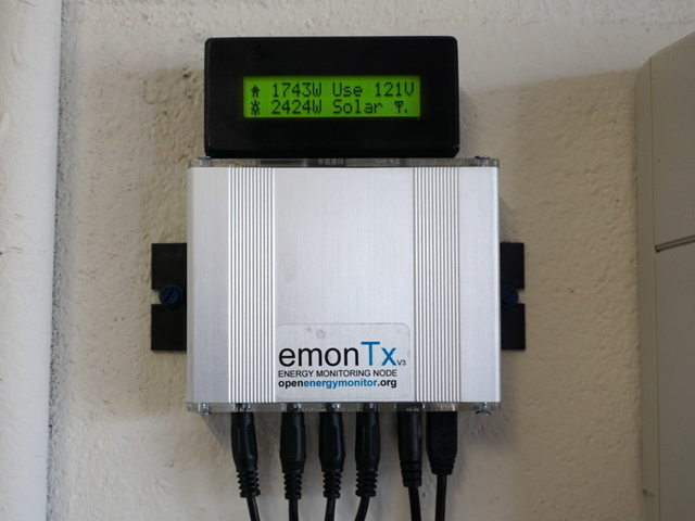
I recently had solar panels installed and the new meter from the electric company meant that the EM100 wasn’t going to work any more so I set to work installing the EmonTx. The Tx itself also has a DS18B20 jammed into the phoenix screw terminals. The case had to undergo a 1 minute modification with a circular file to get it to fit in the slot sideways (sorry no photo of that).
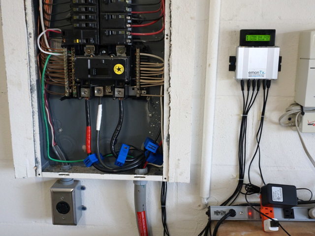
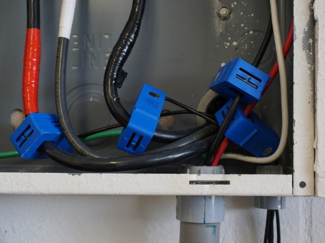
For those that aren’t as into being an electrician as electricians are, to run the CT wiring out of the panel I used one of the 1/2" knockouts, with a schedule 40 PVC male adapter, a 1/2" conduit locknut, and a 1/2" rigid conduit insulating bushing (although I don’t believe you need this last piece). It took a few trips to the hardware store to get the right combination.
One of the things that was holding me back in getting an EmonTx originally was that it transmitted RF so you needed a receiver that was just tasked with uploading the data to EmonCMS. A Raspberry Pi, wifi adapter, 5V supply, SD card, and yet another little machine sitting somewhere in my house. When I saw the EmonESP blog post I knew it was exactly what I was looking for and it worked immediately with no fuss no muss.
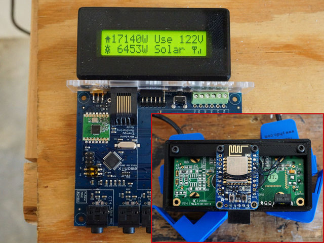
Wait second, the EmonESP doesn’t have an LCD on it! Well I felt bad about having the ESP with all them there GPIOs just not doing anything, and I needed to make a little case to put over the Adafruit Huzzah breakout module anyway so I just wired it up to an LCD I had here and 3D printed a mount and case.
My solar panels ended up putting out too much power though for CT4 on the EmonTx so I replaced all the burden resistors with different values while I was at it. 27 ohm 1% for CT1 and CT2 (house import power), and 47 ohm 1% for CT3 and CT4 (solar generation) which gave me roughly 81A and 47A current limit respectively.
I would be happy to share the source code to the LCD display, it adds a file of about 180 lines to the EmonESP scetch, with the majority of that being the custom character definitions for the wifi / house / sun icons which I designed!
LCD / ESP board mount is on Thingiverse
Full sized images Imgur Gallery
Again, thanks for everyone who answered my questions and made this project a 100% success! It might be cool down the road for there to be an EmonTx v4 with no RF69 module and an ESP8266 instead but this is ridiculously easy and cheap to do. I can really only complain about one thing, which is a minor gripe that the FTDI header could be moved 0.1" toward the edge of the board which would allow for a more secure connection to a standard right angle dupont header. I may add a piece of double sided tape to the LCD to help hold it on.
EDIT: I wasn’t sure what category to post this in, so if a moderator wants to move it to where it might do the most good I say go for it.