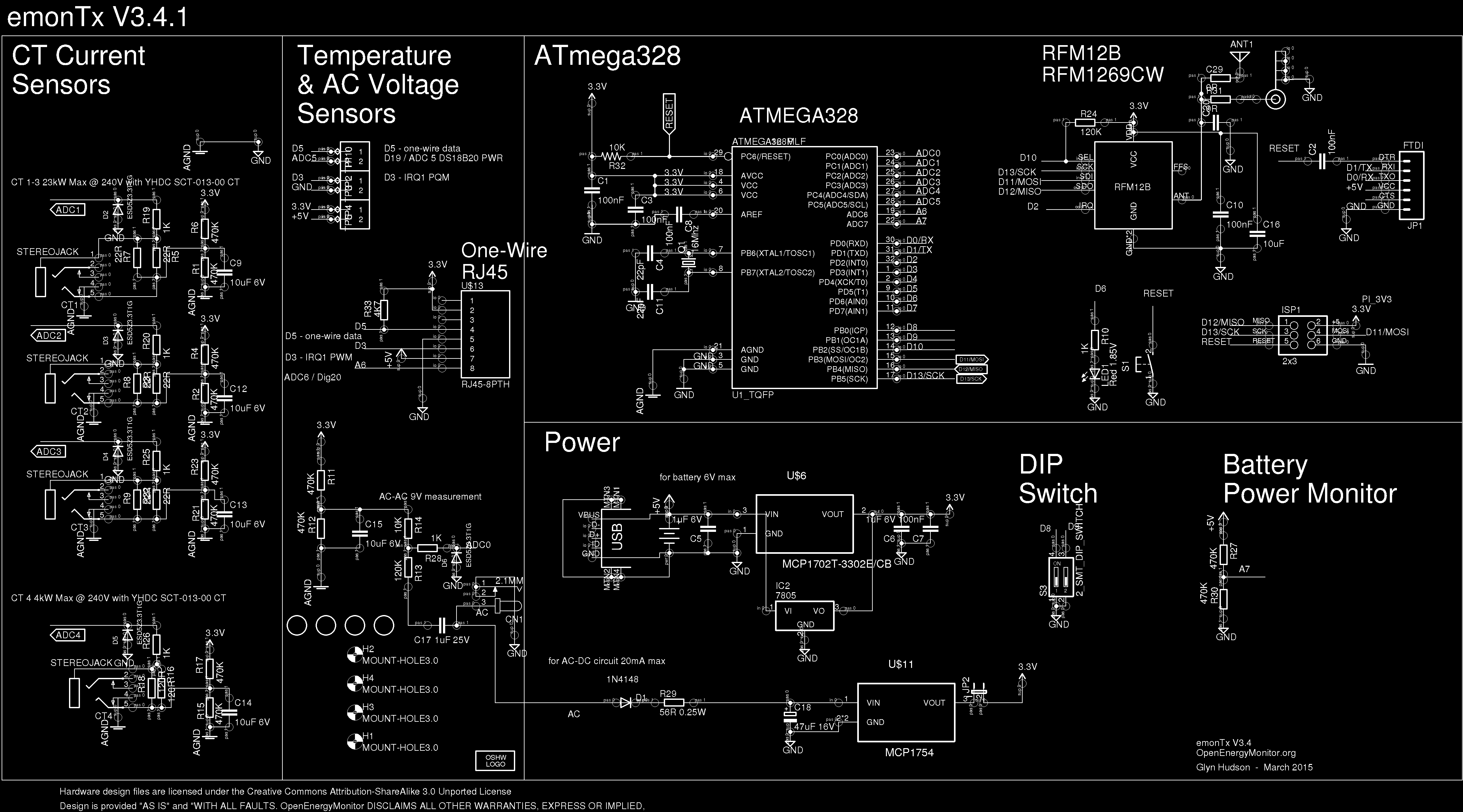
I am fairly new to electronics/hardware and have a few questions to further my understanding of how the emonTx works at the circuit level. The schematic I am looking at, from the emontx github, is below for reference.
Each input for CTs 1-3 has two 22 Ohm burden resistors placed in parallel. Is this to account for power dissipation ratings of the resistors or is it perhaps to help accuracy or noise of the voltage signal in some way?
The ADC inputs for the CTs and the AC-AC adaptor all have diodes which, if I understand correctly, are to protect the ADC by providing a path to ground if the voltage rises above the diode breakdown voltage. Are the 1K resistors (R-19,20,25,26,28) placed before each ADC in order to prevent a short circuit in case of this breakdown or do they serve another purpose? And under normal operation, can we assume that the ADC inputs draw little enough current such that the voltage drop these resistors would introduce is negligible for measurement purposes?
Why do we need cap C17 on the AC voltage measurement section? I know theoretically that a capacitor acts like a short-circuit when an instantaneous voltage change is applied, and in this case we are expecting AC input, so the voltage is fluctuating consistently. Does this mean we assume that C17 acts mostly like a short-circuit?
The Power sections notes “for AC-DC circuit 20mA max”. What sets this limit? Is that the max draw from the MCP1754 LDO?
Any tips/explanations are very much appreciated! Thanks!
1). A true CT outputs a current proportional to the primary current it’s wrapped around. In order to turn that into a voltage that you can measure with an ADC (or voltmeter) you need to put it across a burden resistor. Some “CTs” have an internal burden resistor so they output a voltage proportional to the primary current, but the ones used here don’t so the burden resistor is installed on the emonTX. If you open circuit the output of a true CT (one without an internal burden) then it will still try to maintain the current it’s expected to, but into an open-circuit which results in very high (potentially dangerous) voltages if there is no other protection mechanism. That’s why it’s always recommended that you open up the CT and remove it from the primary cable (or ensure there is no current flowing in the primary cable) before you unplug the CT output from its burden R.
The diodes look to me as though they’re trying to add protection in the case where the ADC input swings negative (i.e. below GND). The 1K series resistor limits the current into the ADC. Normally that current is used to charge a small internal Sample-n-Hold capacitor. The amount of source impedance determines whether or not that cap gets charged in time before the conversion starts. The AVR ADC inputs are designed for signals with a source impedance of less than 10K, so 1K is plenty low enough not to impact normal operations, although you’d have to add it in to all the other series impedances in the signal. You can read more details about the ADC input circuitry in the Atmel datasheet.
But when things go wrong (too big a swing out of the CT) it’s possible that the ADC input can exceed Vcc (or drop below GND). The AVR has internal protection diodes that start conducting at Vcc+0.5V (from memory) but they’re only good for 1mA. The 1K resistor, in conjunction with the other series impedances, helps to limit that current during such a fault condition.
I read the first question to be asking something different so to add to dBC’s info.
Not actually true, 2 are shown on the schematic and there is a place for a through hole resistor (of any viable value) on the board, but only the SMT 22R resistor is fitted. You can remove the SMT burden (or keep it in parallel) and fit another value to change the sensitivity and range of the CT channel (ie if both 22R were actually fitted it would effectively be an 11R burden).
and the “20mA max” limit is the the limit imposed to avoid distorting the AC sampled waveform when powering the emonTx via the same 9v AC Adapter. You could could probably draw considerably more than that with out any “power supply issues” but the voltage measurement would be not be accurate, therefore neither would the power values.
I believe the C17 cap is also there to help reduce that effect, but I couldn’t explain the theory behind it
EDIT - see next post!
Oh no you can’t - the 3.3 V rail will collapse on every mains cycle as the reservoir capacitor empties, most probably resetting the processor. The current is strictly limited, the RFM69 alone is too much at worst-case mains voltage and component tolerances, without any additional current drawn by temperature sensors etc. The series resistor that imposes that limit is there to restrict the dip that the a.c. adapter’s internal impedance generates as the reservoir capacitor charges on the rising peak of each cycle.
Yes - to a.c. The value is quite high - much higher than necessary for amplitude accuracy - to minimise phase shift between the mains and the measured waveform, which is important in real power calculations.
I don’t doubt what you are saying in the slightest, but this excerpt from the emonTx v3.4 wiki suggests up to 60mA can be drawn from the AC:AC without “damage” but with “impaired operation”, Which I would read to mean the voltage sample will be distorted/invalid between when drawing between 10mA and 60mA, not that things would start coming apart at the seams.
Important note regarding powering with AC: powering via AC is only recommended for standard emonTx operation without auxiliary sensors (apart from up to 4 DS18B20 temperature sensors) or equipment (e.g. relay modules) connected. Correct operation via the ac supply is critically dependent upon using the correct ac-ac adapter. If you are using the recommended ac-ac adapter and the current draw exceeds 10 mA and the mains supply is below the minimum allowable, then the circuit operation will be impaired, adversely affecting the reading accuracy of the emonTx. To avoid damage to the emonTx V3’s circuits, the current drawn from the AC circuit should never exceed 60mA - see technical wiki for more info. If more than 10 mA of current is required it is recommended to remove jumper 2 (JP2) and power the emonTx via 5V USB. When JP2 is removed, the AC-AC adapter if connected will only be used to provide an AC sample. It will not power the emonTx.
I rarely power even a basic emonTx from the AC:AC so have no experiences to call upon, I just recalled reading this in the wiki, maybe it needs clarifying further?