Hello.
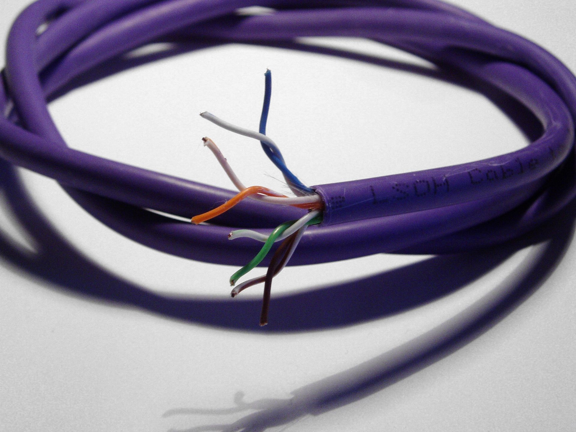
I’ve experimenting with different type of antenna for a emonTH. They supposed to be all 433Mhz . But I’ve get best results only with single piece of wire from Cat5 cable 173mm length.
May be I need some resistor “R2”-location. May be I’ve missed some important part of theory? Why the best result I’ve get with so simple thing.
BTW Is there any difference how antenna and PCB are oriented to each other?

If you look at the circuit diagram, which you can find via “Resources”, you will see exactly what the value of R2 is - 0 Ω - and if you look at R2 & R3 together, you should be able to deduce what their purpose is.
Regarding the antenna, you have found what we already know, that a single wire is best. That is what the output stage of the radio module is designed to match. Ideally, the pcb will act as a ground plane, so orienting it perpendicular to the ground plane should give the best result. Alternatively, you can add a second wire and make a dipole, which might give an improvement.
Hello Rober. Thank you for response.
What about EmonTX C20 capacitor?
It has value “ant tune?” Does it the same value as C29 - 0 Ohm.
What about wire parameters:
- Diameter
- Isolation
- From which point it have to be measured. From RFM antenna pin or from board pin?
- Antenna length formula? On EmonTH I saw what it have to be ~165 mm. But for antenna I saw such formula L = 7500/433 ~ 173mm
Do you know why there is a difference ~8mm?
I’m away from home at the moment, so I don’t have an emonTx to look at. @glyn.hudson should be able to answer this.
The other questions:
- It makes little difference. If you want the aerial to remain in position, then a solid-core wire is best. However, because my emonTx’s are only ever used for answering questions like yours and testing sketches, when the solid wire breaks, I replace it with something like 7/0.2 mm stranded.
- Do you mean isolation from other metalwork? Yes, you need to keep it away from other metalwork, unless you’re talking about a ground plane.
3 & 4. The PCB legend says 175 mm. It should be measured from the RFM pin, but in practice it seems to make little difference. There’s no detailed information that I’ve seen about the requirements, but if you have suitable RF test gear, you could start long and trim the length for best signal strength. It may well be that the shorter measurement is from the board and takes account of the short track from the module. Or the difference could simply be a mistake.
Sergi,
Given English isn’t your native language, this may be nothing more than a guess on my part.
By any chance, did you mean insulation?
Hi Sergi,
Since I don’t know how the EmonTH antenna length was calculated i.e. was the length simply calculated, or was it determined empirically, I can’t say for sure why the label reads 165mm
One thing for certain, though. Insulation does affect antenna length. In general, an insulated antenna element will be 3 to 5% shorter than an uninsulated element cut for the same frequency.
Ref: antenneX Home Page
The effect is more pronounced with Cat 5 cable.
Ref: Velocity factor - Wikipedia
Regarding the wire you used for your antenna – did you remove it from the cat 5 cable bundle?