Hi
We are investigating energy monitoring solutions and like the open approach of emonPi. Our application makes the use of Rogowski coils (instead of CT) necessary and I am wondering if it is possible to connect these measuring devices to an emonPi (or emonTx) as well or if the inputs are limited to CTs. Would be great if somebody can share his experience with Rogowski coils and emonPi. Thanks in advance.
Andre
I haven’t heard of anyone using a Rogowski Coil, you might need to do some interfacing. Both the emonPi and emonTx use the same input circuitry. You’ll need either a floating output of 50 mA rms, or if you remove the burden resistor, a floating voltage of 1.1 V rms, or you can have a ground referenced voltage but you must bias it to +1.65 V d.c. (i.e. so that it sits in the middle of the 3.3 V supply to the ADC, and in that case you must check the circuit diagram for connections, because the input is on the plug sleeve, and you’ll need to bring out the power supply GND).
As a matter of interest, what makes a Rogowski Coil necessary (if it’s not commercially sensitive information)?
Robert, thanks for your detailed anser. I will have a look at the input circuit and see if I can modify it according our needs.
We have some space limitations at the installation and Rogowski coils would therefore be much more flexible to wind around the primaries without modifying the installation itself.
You might already know this, but in case not, you’ll need an integrator as well since the output voltage of the coil represents the rate of change of current while the OEM gear will be expecting a signal that represents the current.
I know this is a very old thread, just wondering if you were able to successfully interface a Rogowski coil to emonPi or such? I need use a Rogowski as our main power has bus bars instead cables. So there is no other way to get a current sensor on it.
Surely you can get a c.t. to fit almost any size of busbar? What size are your bars?
There’s a Wattcore 2000 A (WC6-2000) with a 2.0” × 5.5” aperture, you can use the 1 V output version directly (but it’s custom made). All you’d need to do is remove the internal burden in the emonPi.
What the emonPi & emonTx will need if you can’t get one with a 50 mA secondary (highly likely) is a burden external to the emonPi/emonTx that develops about 1.1 V at rated current (and of course your c.t needs a VA rating to match).
Or, instead of the burden or if you have an existing c.t. on the bars, use a 1 A or 5 A : 50 mA c.t. as an interposing c.t. straight into the emonPi.
We’ve not seen Andre Meyer since that post.
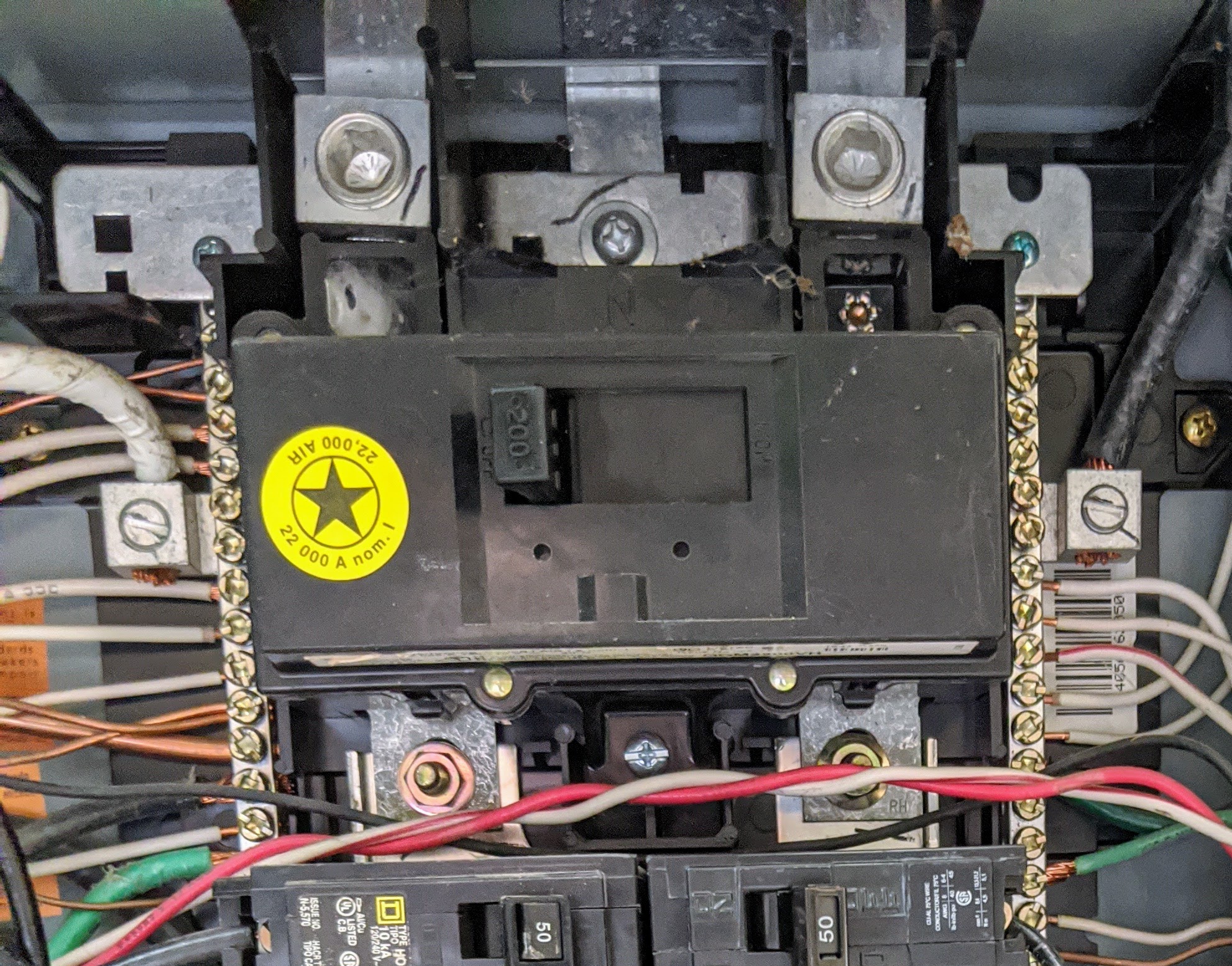
There is no room to fit a regular CT.
Yeah the rogowski coils I can find produce output proportional to rate of change in the current flow. There is a pre-amp to convert that to voltage proportional to current flow through the conductor the coil is fitted around. But I would need to calibrate it with EmonPi/Tx and this is where I was hoping I could find info from others who may have attempted the same thing.
I see what you mean. I wouldn’t have called those busbars, they’re only the lugs bolted together.
That will incorporate the integrator that @dBC mentioned.
The emonPi’s input is designed for a c.t. The plug sleeve is the input, the plug tip is the “earthy” side but sits at +1.65 V d.c. above emonPi ground. It expects a 0 - 1.1 V rms input on the plug sleeve. You must remove the burden resistor inside the emonPi.
This implies that your pre-amp and its power supply must not be ground-referenced, or if they are, you must a.c. couple the input to the emonPi and connect the grounds.
The calibration constant in the emonPi front end is the current that gives you 1.0 V rms across tip and sleeve of the input socket (± the ADC reference tolerance, etc).
Thanks for the info Robert. Yeah not really the busbars like most people would imagine but it is the closest thing I could think of calling it. I think I should be able to a/c couple the integrator’s output. Once I have a pre-amp integrator that outputs in the range (0 - 1.1V) I can calibrate it. A lot of rogowski coils and pre-amps combinations I found output 0.333v @ 200A. But I suspect I can adjust the gain to get 1.1V. It is going to be an interesting project. Or may be I just buy a Emporia Vue 2 who apparently also sell rogowski coils for 200A busbars: Emporia Vue 200A flexible Current Sensors for Smart Home Device Energy – Emporia Energy
The two flat metallic objects at the very top of the picture just above the large hex screws, are indeed the L1/L2 bus bars. The two large screws secure the main breaker to said bus bars.
The flat metallic “straps” under the smaller screw head in between the L1/L2 lugs are the Neutral connection and bus bar. The branch circuit neutral wires and attachment point bus bars, are visible immediately to the left and right of the main breaker. (the two vertical rows of screws)
Real busbars are at least 10 ft long. 

You really need to look at the circuit diagram for the front end:
Thanks, I will be looking at the circuit. Right now I am using emonESP board with two sensor inputs.
You might also want to read this:
Most of the time 100A would be enough for us. But we have two dwellings served by the same panel (via two other sub-panels one 50A, another 100A and the remaining circuits in the main panel). At the peak usage we can exceed 100A. So I will go with 200A sensors.