I have an Emon PI (pre-built, purchased in Oct 2021) that has worked fine monitoring my household consumption using a CT 1 and the voltage sensor.
I have recently installed a Solar PV system and am now trying to use CT2 to measure my solar generation. Both CT1 and CT2 and 100A/50ma CT’s with fitted 3.5mm plugs purchased from Open Energy Monitor.
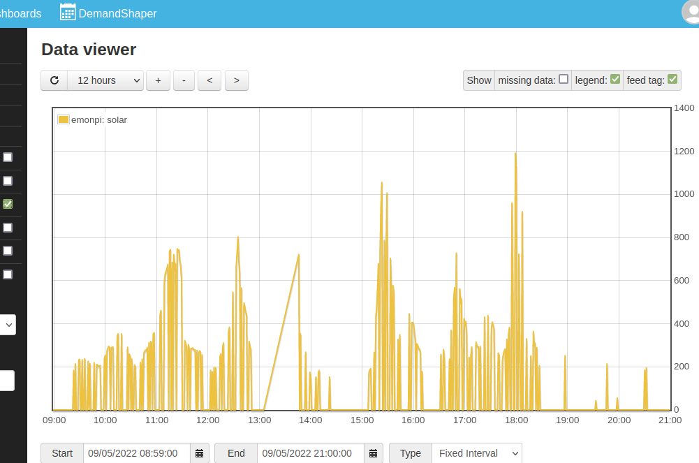
Power 1 works fine, but Power2 suffers continual dropouts of the signal, see image, these are also visible on the LCD so it is definately the emonPI not reading the power.
I have swapped the CT’s - the problem is still Power 2, I have even made a test rig and connected CT2 round the live feed to a known load (2kw heater) - Power 2 reports correctly but still suffers dropouts.
Is there any way to diagnose the problem further, I’m confident in SSHing to the emonpi so can run command tools etc but no idea what to do.
--------------
Emoncms Version low-write 10.8.5
Components: Emoncms Core v10.8.5 | App v2.3.4 | EmonHub Config v2.1.1 | Dashboard v2.1.5 | Device v2.1.3 | Graph v2.1.1 | Network Setup v1.0.2 | WiFi v2.1.0 | Backup v2.3.2 | DemandShaper v2.2.2 | Postprocess v2.2.2 | Sync v2.1.1 | Usefulscripts v2.3.7 | EmonScripts v1.4.0 | RFM2Pi v1.4.1 | Avrdude-rpi v1.0.0 | Emonhub v2.3.1 | EmonPi v2.9.4
I take it the gap between 13:05 and 13:45 (about) is when you shut down to swap things, and your problem is the much shorter low periods that can’t really be distinguished at this scale?
By this you mean that when you swapped the c.t’s, the fault remained with CT2 Input and “power2”?
And the PV feed was uninterrupted when it was in the CT1 input?
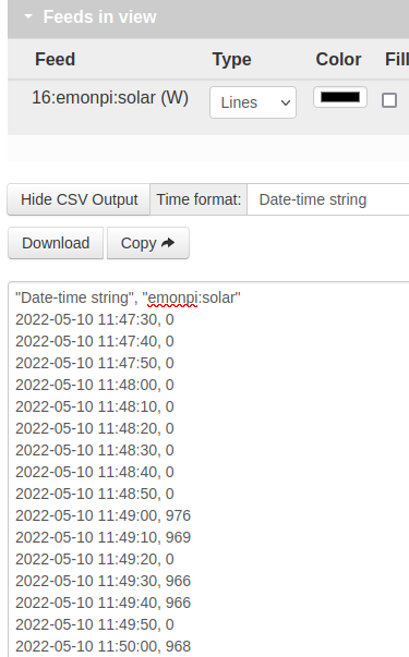
If you expand the graph time-wise so that you can see individual values ‘pop up’ when you hover the mouse cursor over them, are the zero values actually zero, or a small number (less than 20, most likely a single digit)?
Do those agree with what you see in the emonhub log?
What do you see if you create a Feed for power1pluspower2 – does that show dips in the curve that coincide with Power 2 dropping?
I’m inclined to think this is a hardware fault, not software. It could be the input socket itself (assuming the c.t. on the main incomer also misbehaved when plugged into the CT2 socket), or it could be another component around there.
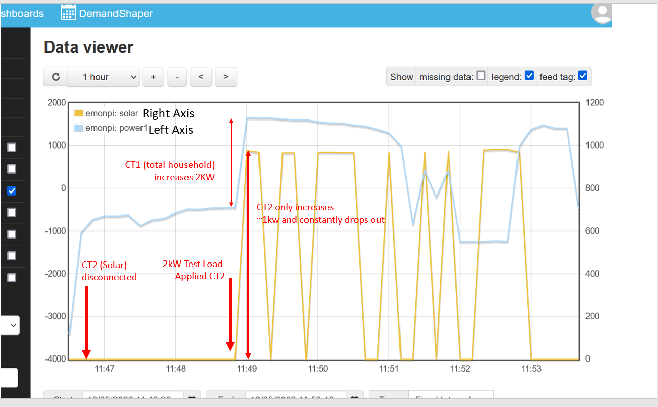
Attached gives a bit more detail - this is the test situation
CT1 socket - on the meter tails as has been for 6 months “power1”
CT2 socket- removed from solar feed and put on live feed to a 2kW heat gun, also monitored via a plug in socket monitor. “solar”
Turn on heat gun
Socket monitor shows 2082 W
“power1” increases from -450 to +1600 showing the load
“solar” only increases by ~950W and the signal continuously drops out to 0 - it is Zero, not a small number, you can also see it as Power2 : 0 on the LCD.
I have previously swapped the CT’s and the problem is definately related to the CT2 socket. There are was no physical movement of the cables during the test.
If it is a hardware fault I am a bit disapointed - it’s the first time the CT2 socket has ever been used! I purchased in in October Last Year to get some consumption data ahead of my Solar PV system just installed.
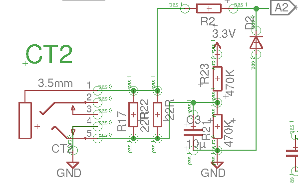
Does anyone know about a warranty repair? Alternatively are there any schematics / PCB layouts as PDF I can use to troubleshoot myself?
Alternatively (and I find it easier to use) get the free Eagle CAD program and download the files for that.
I’ve got to add, this is the first time I’ve seen this particular fault reported - I think it will be hardware, but I’m not absolutely sure what mechanism could give the exact symptoms you’re seeing. It really does appear to be sending zero values.
One thing I forgot to ask - what is the feed interval? The power sensing front end (the “Emon Shield”) should be sending data every 5 s (just under), so the feed interval should be longer than that.
You can see the time the data send by the Emon shield arrived in emonHub from the emonhub log (down to ms), and hovering your mouse over the Feed on the Feeds page will give you the Feed interval.
Do you by any chance have a lot of emonTHs connected as well? Too many of those could stretch the reporting interval to greater than the feed interval, and give the effect you’re seeing. But I’d expect that to show on Power1 as well. I assume, as you haven’t mentioned it, there are none.
Feed interval on the emonPI is 10 seconds, there are 7 feeds the standard 2 CT’s and things calculated off them, cumulative kWh etc.
There are no emonTH - a weather station makes 4 http calls every 5 minutes and there are three event http driven calls from a second PI that picks up the zone valve positions of my hot water valves a few times a day but that’s it.
I think it’s hardware - will have a look, but will be next week - then perhap contact Magani. It’s irritating as I bought a pre-built one rather than building one to save myself the time!
You’re resolutely not looking at the emonhub log, which is closer to the source of the data, so will give me a much better idea of what’s going on.
I can understand, but it’s rare to encounter a hardware fault in the emonPi (or indeed in an emonTx) itself. But you probably made the correct decision nevertheless, because when this was more of an electronics constructor’s forum, there were many prototype “emonTx’s” made and I could almost always say that every complaint of circuit noise - non-zero readings when no power was flowing -involved a self-built unit on Veroboard or similar, and some even were plugboard.
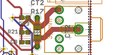
Been busy, but finally had time today to have a look at this. Carefully opened the emon PI - see attached photo of the 3.5mm PCB Mounting. the test plug is in CT2 (the channel that under reads and keeps dropping out). CT1 is the empty socket on to the right.
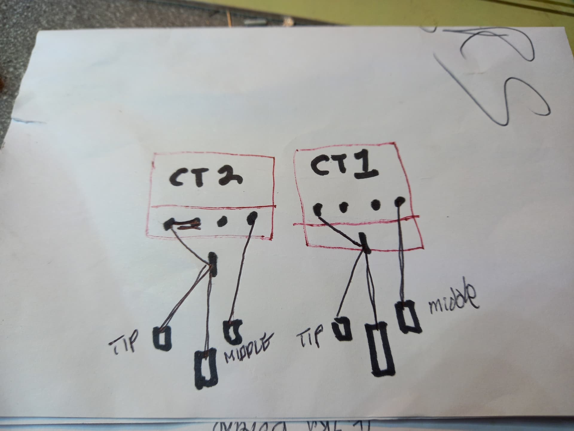
There is a solder bridge between the two left hand pins of CT2, there is no bridge between the equivalent pins of CT1. I then tested the continuity between the test plug and the 5 pins for each socket, see sketch on second pic.
The two left hand pins of CT2 have continuity (obviously as solder bridge!) the two left hand pins of CT1 do NOT have continuity.
I am tempted to conclude the fault is the solder bridge, but before I reach for the soldering iron does anyone have any thoughts?
Pin 4 is the ‘break’ (inner) contact, and it’s grounded to signal “no plug inserted”. The tip is actually an a.c. ground, the input current is on the sleeve and the ring (2 & 3) is not used. The problem is, the library detected “no plug present” so it reported zero current and zero power. Without that logic, the input would have been half-wave rectified because the bias voltage was grounded.
(Note: There aren’t two burden resistors - the second is empty for a second parallel wire-ended component if required; and the grounding on pin 4 is badly drawn - it should be over to the right of the pad.)
@Gwil I am keen to get the new data as quick as possible with no gaps in the data of the working CT1.
Shortly after my new solar PV install my supplier installed smart meters, they won’t connect to the network so both they and I are blind, not even a display on the meter. As we wait patiently for their contractor to fix it I want the data from the Open Energy Monitor CT1 as my own record of imports even should my bill come down to estimates!
I will have a go removing the bridge - if it does not work I will contact you to arrange return.
Thanks for the help - PS love the location I spent many happy hours climbing round your way when younger.
Final update on this - further investigation on the solder bridge revealed there was indeed a tiny break, using the two probes on the DMM if you pushed “outward” resistance would go from dead short to 2-3k. This perhaps explains the intermittency - as it warmed up in case it would also probably change a bit?
Bridge removed with solder sucker, reassembled and all now seems to be working. Thanks to those who helped resolve it.