Received my EmonPi, EmonTH, and EmonTx smt shield. Most everything is working, except for the CT inputs on the EmonPi. Temperature and humidity feeds work with the EmonPi, EmonTH and EmonTx. I can log data from my Nest thermostat. The EmonPi UI works fine, ssh login, etc.
The CTs work ok on the EmonTx but when setup on the EmonPi two things happen
No values appear on emonpi power1 or power2
Vrms drops from (approx) 67V to 20V with one CT and about 6V with both
When the same CTs are plugged into the EmonTx they produce values both by themselves and when attached to 240v hot leads.
The 9VAC reference is connected to the EmonPi and the EmonTx was powered via USB.
Did I miss something in the EmonPi config or is there a problem with the CT monitors on the EmonPi ?
Sorry to hear your having trouble. The CT’s and AC-AC need to be attached before first power up, ensure 3.5mm jack is pushed fully home. The CT sensors must be clipped round either the Live or Neutral cable (not both!).
Does pressing the black pushbutton advance the LCD display?
Primary house feed conductor diameter, with insulation, is less than the inner diameter of the CTs (~10.5mm)
CT was/is clipped to individual 240V branch circuit leads, either red or black conductors.
AC-AC adapter is the 110v : 9v one supplied from the store
EmonHub config is calibration=110V. Although initially I had it set to 230V.
I think the CT plugs are pushed all the way in. The LCD reports CT detected on boot.
The pushbutton generally does advance the display.
The button/LCD freeze seems to have been only the last cycle. I had to use the web admin UI to request a shutdown.
Current reboot has the button/LCD cycling. At least right now
My thought was since all the shield CT ports were working and all the CTs I have work with the shield the CTs are ok. I have three. One from you guys and two that I had previously from Seeedstudio (same manufacturer, same part number, grey lead).
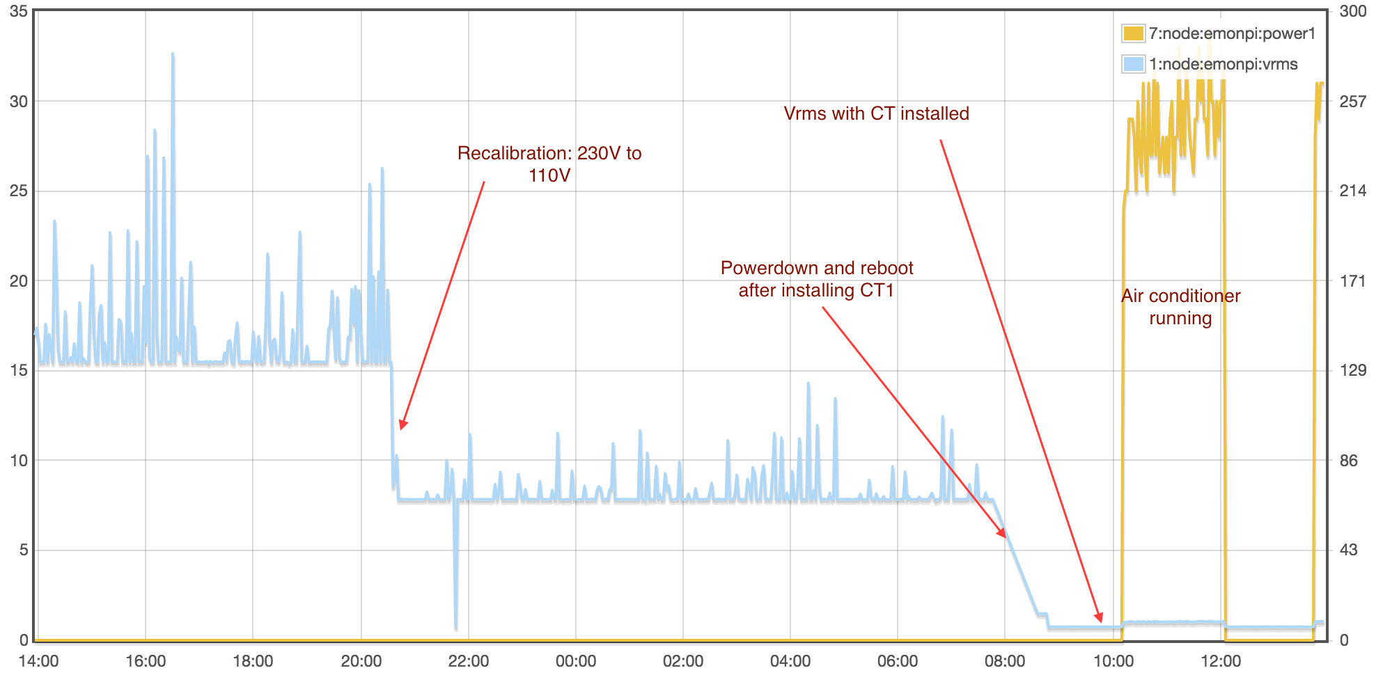
I did some further investigation as follows. I shutdown and reinstalled a CT on our air conditioner circuit. I’m still seeing the Vrms pulled down when the CT is installed but when the AC kicks in I do see power usage being recorded. I’m still concerned about the Vrms behaviour, and I haven’t tried the CT2 circuit again, nor having two CTs installed. Have to validate the AC power usage numbers too.
Not entirely feeling warm and fuzzy and I don’t want to leave it alone at this point.
I don’t think this is the Vrms being ‘pulled down’, the Vrms reading should be correct when the CT is connected. The Vrms and CT readings work together to calculate real power. Please ensure both sensors are connected before power up. Do you have another measuring device to test against? It looks like the unit is reading correctly.
The unit is not designed to read Vrms without the CT connected.