Hi all,
Thanks to forum help, my emonPi North America setup is very close to functional. Thanks for taking the time to help untangle my issue, below:
Setup/Scenario
- code upgraded to latest version from May 2016
- config user account, timezone, static IP info, and “calibration=110v”
Also, Setup>emonhub>edit config as follows:
[[5]]
    nodename = emonpi
    [[[rx]]]
        names = power1,power2,power1pluspower2,vrms,t1,t2,t3,t4,t5,t6,pulsecount
        datacodes = h, h, h, h, h, h, h, h, h, h, L
        scales = **192.31,192.31**,1,0.01,0.1,0.1,0.1,0.1,0.1,0.1,1
        units = W,W,W,V,C,C,C,C,C,C,p
****end emonhub config edits *********
NOTE: value 192.31 taken from chart - 7500 / 39 ohms = 192.31
Reference: https://openenergymonitor.org/emon/buildingblocks/EmonTx-in-North-America
Connect per instructions, power up, AC-AC adapter recognized, temp probe recognized
PROBLEM
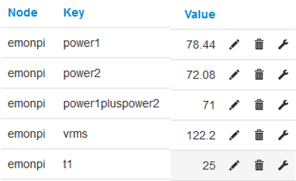
Go to Setup>Inputs
- emonpi power1 = 0
- emonpi power2 = (varies from ~24,000 and 45,000, depending on whole-house current draw, I believe)
- (BTW, power1pluspower2 = 127, and vrms = 121.5 to 225…it tracks the CT2 value)
- (BTW#2 - its a typical Florida “winter” at 21C, so no heat or A/C running)
Troubleshooting
#1
Swap current sensors (sensor formerly in CT1 moved to CT2 input, vice versa)
CT1 continues to read zero; CT2 reads a negative value
In other words, symptom follows CT1 input, both sensors seem functional
#2
power down emonPi, disconnect everything
Connect meter to male plug, connect to CT1 - reads the expected 39 ohms
Connect same to CT2, reads the expected 39 ohms
Question
the two possibilities I can think of:
- I damaged the emonPi unit during the desolder 22-ohm / solder 39-ohm (I’m pretty good with a soldering iron, have a nice Hakko soldering station, examined w/magnifying glass, and all looks OK, but still a possibility)
- My ignorance of emonPi code has led me to misconfigure or fail to configure something.
Of course, I hope for the latter. If so, any pointers?.
If the former, can I purchase just the emonPi board as a replacement?
Thanks much!