I’d appreciate confirmation from the group on a) wether the emonPi is compatible and b) the hardware I’d need for the following setup and requirements (before I splash out further cash)?
I have a fairly unusual home electric setup due to our rural location with:
a two phase supply (2 x single 100A phases split between the internal and external electrical items)
a 6Kw Solar PV array split 50/50 between the 2 phases
a Solar iBoost driving our hot water immersion if we are net exporting electric on phase 1
My requirements are simply to be able to see if we’re net exporting or importing on each phase (ignoring the iBoost) individually so I can proactively switch items off or on to make use of the PV generation.
I’ve tried a few different solutions and currently have a Geo Chorus II installed and a Lightwave RF energy monitor. The Geo uses the LED on the electric and generation meter so that’s only telling me my aggregated usage and generation for the whole property - not per phase which doesn’t help me actively plan. Note also our Solar iBoost has to be factored in as that skews net import/export when its on if it detects net export.
I’m fairly technical and already have a Raspberry Pi running other services so the emonPi system looked interesting when I came across it this week.
I’m assuming I’d need:
an AC clip per phase
a voltage sensor adaptor per phase?
an AC clip to put on the Solar iBoost to know when that’s on?
But is the emonPi clever enough to present the two phases or would they be considered two distinct systems for the purposes of the UX?
Given my meter LEDs aggregate both phases is that a problem for the emonPi?
How would the emonPi factor in the Solar iBoost?
You say you have two phases - you appear to be in the UK, do you really mean two phases or two feeds off the same phase? (The test is, do you measure 0 V line-line across the two supplies, or 415 V?)
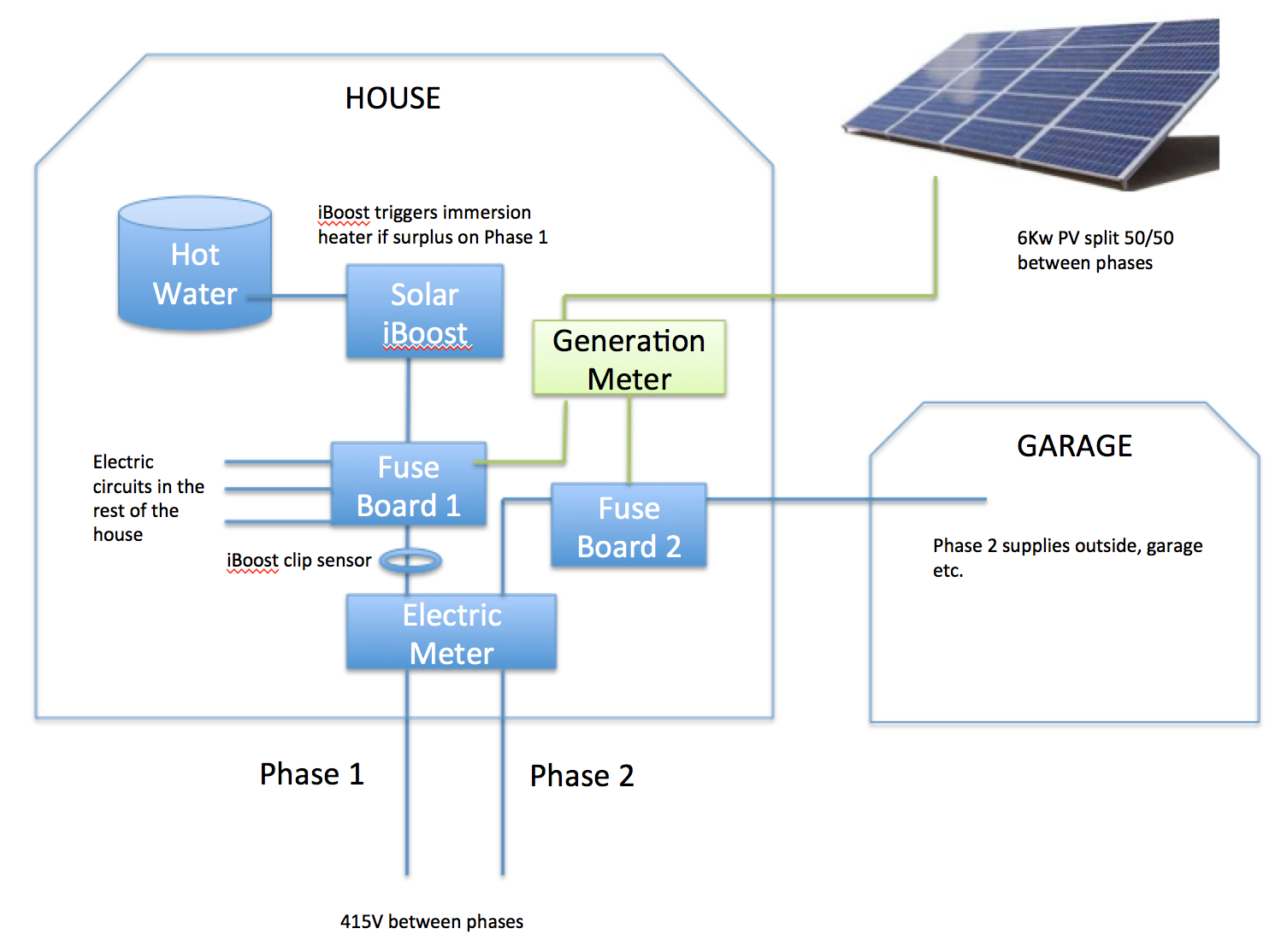
I think a single line diagram showing how and where everything connects would be helpful.
On the face of it, it looks as if you need an emonPi plus an emonTx, because the Pi has only one voltage and two current inputs (ignoring pulses, which you say don’t tell you what you want to know).
EmonCMS is certainly capable - given enough separate pieces of information, like currents and voltages and their phase relationship - to show you exactly what’s happening pretty much in real time.
The attached drawing shows my understanding. You’re correct I’m in the UK and I know we have 415V between phases - which is why the installation is designed to segregate uses of the two phases to minimize someone experiencing 415V.
How would the emonCMS handle the Solar iBoost - given that is essentially misrepresenting the situation given the phase 1 flow may look almost 0 net export when in fact the solar iBoost is eating say 100W and therefore I could use that 100W elsewhere?
So my first assumption was correct, to read real power (hence the direction of power flow), you probably need an emonPi plus an emonTx, one on one phase and one on the other. Each will monitor its own phase voltage with an ac adapter. Then you have two current inputs on the Pi and 4 on the emonTx, so it looks to me as if the Pi should go on the garage phase with one CT on the grid connection, the second on the PV infeed but on the supply side of the generation meter. You do the emonTx similarly on the house phase. In each case one CT will give the nett grid power flow on that phase (and you add the two in emonCMS in the Pi to give total nett grid power) and the other two CTs give you the respective generated powers, which you can similarly add to give the total generated power.
The emonTx still has 2 spare current inputs that you can use to add detail should you wish. Obviously you can put one of those on the immersion feed so that you know exactly what the iBoost is doing, which will tell you when you can manually divert that extra load. In effect, excess power available is the nett export on that phase plus the immersion load, if I understand correctly.
(Note in principle you can put the CTs anywhere and do the sums appropriately in emonCMS, but I feel it’s safer (more accurate) to measure a small value and add it to a larger one than to measure two nearly equal large values and rely on the difference being accurate.)
Note that I’ve said ‘power’ each time, but emonCMS will accumulate the values to give you energy as well, which if you feed in the optical pulses can be cross-checked! (Probably not advisable as they’ll never agree, but with careful tweaking of the calibration, you should be able to get close.)
Having read a little on emonCMS I haven’t seen any examples where multiple distinct ‘phases’ are displayed. I’m specifically interested in how the emonCMS UX will handle my (complex) setup for the purposes of easily seeing net export on either phase easily e.g. does it provide two distinct charts - any suggestions on where I can see that illustrated?
…and I wanted to check if a CT clip will work around a 3 core cable from the Solar iBoost to the immersion or will it only work if clipped around the live wire element (somehow)? Note I did a test with my LightwaveRF energy clip around the cable from the Solar iBoost and it just reports “0”.
Not offhand. But you can make your own graphs to display whatever you want. If you go back to the old forums and “EmonCMS Showcase”, you may well find some inspiration there.
No CT will work like that. All will report nothing on a two- or three-core cable. It’s explained in Resources > Building Blocks. You must get at the cable inside one of the items where you can see just one of the current-carrying cores. You must not, outside a piece of equipment (which might be another box), remove the protective sheath around the cable (the grey plastic if it’s twin & earth) to expose the coloured cores. You could measure the input side of the iBoost, because I doubt that it will consume a significant amount of power on its own.