EmonPi and emonTX3 initial setup in 3 phase setup with solar

Hi there
I have had my EmonPi running since 2018 but it started to miss some sensors for some reason, so I have opted to start from scratch.
So I have downloaded the latest firmware, wrote it to the SD card, and I am now trying to “restart” the whole setup based on “older” hardware… so the EmonPi and three EmonTX v3 and a bunch of current clamps…

If someone can guide me to the best working firmware and setup for my little config.

I live in Denmark where we have 3 phase power 230V. So that’s why I have the three EmonTX v3, which is used to monitor a phase each. They are also powered by the AD adapter connected to the same phase as it is monitoring (this should make the measurement more accurate).
Just so complicate things, I also have some solar power on my roof, where my inverter provides 3 phase power to my house.
So I used to monitor my 3 supply phases and the 3 solar phases, which made sense at the time.

Now that you know my setup, what would be the best firmwares for the emonTX v3 boxes? (I can see that there are 5-6 to choose from).
Also do I have to toggle the dip-switches in the emonTX v3 to the same channel or should they be different? (there are only two channels, and I need 3 devices… (is this an issue or can they share channels))
Right now as I test different firmwares I am having the issue that as I flash the new firmware, the box reboots, and seems to become online and I can see it in the webgui… but I then disconnect it from the serial programmer (and the emonPi) and power it via the AC adapter… it doesn’t seem to ever get back online in the GUI… The red LED blinks on the unit but no data is sent or recieved… Maybe this is an issue with the wireless antenna/logic on the emonPi?
This lead me to a post where it was stated that the emonTX could be connected via USB… but maybe this only works with the v4 ? Because I don’t get any USB serial adapters when the unit is connected… (tried “lsusb” etc… nothing…)

Suggestions are welcome… I think I just need to get the emonTX boxes flashed with the same firmware version, and communicating to the emonPi and then I am golden :wink:

Welcome back!

It’s probable that I originally wrote the sketches for your emonTx V3. However, @glyn.hudson or @TrystanLea made changes while I was working on the software for the emonTx4, changes that I haven’t fully looked at yet. So they are best placed to recommend which sketch you should use.

However, I can answer some of the other points with a degree of confidence.

You are correct when you use one emonTx V3 to monitor everything on one phase, house and solar, so all the c.t’s and the a.c. adapter are looking at the same phase.

Each emonTx must have its own Node ID - this is how your emonPi knows where the data came from and which phase it belongs to. You set the NodeID in the sketch, and then you can modify the number with the DIP switch. But you only have the choice of two NodeIDs with the switch, so you can change one with the switch, the third you must change in the software you load into the emonTx V3.

I think you are correct, this will probably be because it is using a different Node ID which you don’t have in the emonhub.conf file in your emonPi.

It can be, but you will need a serial to USB adapter (“Programmer” in the OEM Shop) for each emonTx you want to connect this way. If you have been using the 433 MHz ISM Band radio until now, you should probably try to continue with that unless there are problems. The USB socket is only used to supply power.

You will need a programmer in any case to load the changed sketch into the third emonTx.

Well… I am wondering if I should start over once again, as I have a device that keeps popping up no matter what I do… I have deleted it several times, and made sure that nothing is powered… I think strange thing is that it is called emonTX4 (and I only have v3) maybe I tried to configure a v3 device as a v4… but why can’t I just delete it and start over? No matter where I delete it from (devices or inputs) it just keeps comming back… (the inputs are not updated of cause…)

I think this might be a fault in emonCMS, which “intelligently” tries to create an input when it sees some data on the radio channel. It might even be coming from a device that is not in your house! I, and other people, have had hundreds of ‘phantom’ devices appear like this.

If you look at the top of your emonhub.conf file, you will see this a few lines down:

[hub]
    ### loglevel must be one of DEBUG, INFO, WARNING, ERROR, and CRITICAL
    loglevel = DEBUG
    autoconf = 1

Try setting autoconf = 0

1 Like

Hi Robert, I remember your name from back when :wink:
You are right about the way I want to monitor my power… two clamps per emonTX.
I might also use a 3rd clamp to monitor my EV charger… if possible… it’s of cause 3 phase, but 400V (11kW) not sure if it makes any difference if I just have a clamp on each phase.

So I was hoping that I could just write one of the FW from the web-gui into the emontx without having to compile my own firmware… (Can you please point me towards the best suited firmware). And there are no way that one can change the ID of the emonTX via the seriel port connected to it?
I am pretty sure I have never changed anything in emonhub.conf file before… but I will give it a go :slight_smile:

OK… you might be right that it is not from my house, or it may be from some of my other devices… doesn’t Phillips Hue use the same freq.? :slight_smile: But how do I “find” my devices once I have written the new firmware to them?

Even with the autoconf set to 0 and a reboot, the damn device is still there, and cannot be deleted :wink:

Your electricity supply is 230 V line - neutral, but 400 V line-line (230 × √3 = 400, nearly). So treat it the same as your solar.

You could, when I wrote the software. But I think this is where some changes were made.

It is a matter of knowing which are the default Node IDs that the sketch uses (these have changed over time) and making your emonhub.conf file fit the sketches. We will know all when we decide which sketch you need. Did I understand correctly that you have started with a completely new emonCMS on a new SD card?
And do you have a serial-USB programmer?

Yes I took a backup of the old SD card, and overwrote it with the latest image.
I am thinking maybe I should do that once more, to clear up any “strange” configs that I may have done… (ie. the strange device that keeps popping up).
And yes I have a USB programmer… I have been testing a few of the firmwares available via the update page and programming it via the emonpi… If needed I should be able to do the same from my macbook if we need to compile with ID changes and all…

People who know recommend you start with a new SD card, because they do wear out and you can lose all your historical data when this happens.

OK, I’ll look for the correct sketch for you to load a little later, because there are some tests I need to do for the man who’s doing the software for the emonPi3. Can you confirm your emonTx’s are V3.4, and not V3.2, because that will make a difference.

Two are 3.4.3 and one is 3.4.2 (from the board)
Please remind me why I cannot just use “any” of the firmwares and read the values from the clamp connected? Isn’t the 3phase-specific firmwares for if you want to read all 3 phases with one emontx ? Or have I misunderstood this? (It was a long time ago, I’m surprised you remembered)

About the device that keeps comming back… it seems that if I delete the device from the devices menu… it stays away (as I refresh the page)… if I then go to the inputs (where it is still pressent) and back to devices, it is back again… :slight_smile:

Correct.
But my problem is, I don’t know what is presently available either on Github or pre-loaded in your emonCMS – this is where I got left behind while working on the new software. I need to check what’s available now and what it does.

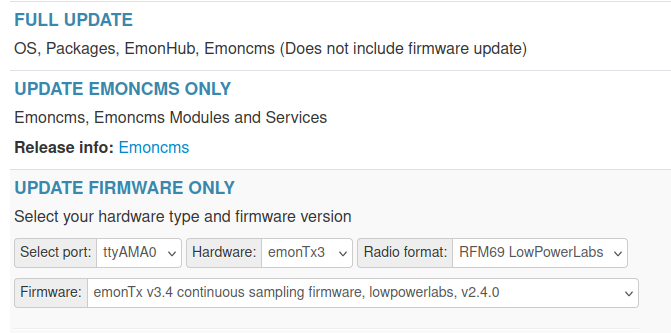
On the surface, it would appear to be this:
image

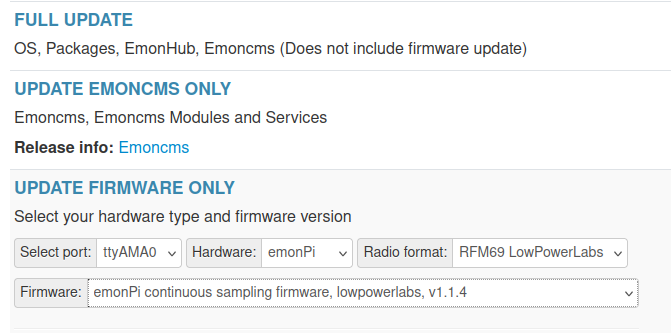
and you need your emonPi to be loaded with this:
image

but don’t know.
As you are starting with a new installation, I recommend using LowPowerLabs for the radio option.

OK, I will start with getting one to work (with the same LowPoweLabs FW) written from the web-gui to both the emonPI using the local seria l port, and then to the emonTX using my USB programmer connected to the emonPI. I will then make sure the next emonTX has another ID set via the dip-switch. And I guess we need to “fix” the third one to have another ID some how?

About the ghost-device, I now had enough, so I will nuke the installation fresh… it makes no sense that it just pops up only if I choose to visit the inputs page… :slight_smile:

OK, I haven’t wiped my emonpi just yet, I wanted to update the emontx units first…
That’s all done, but I am trying to set another ID on the 3rd node, and trying to use the “+++” at boot time… but doesn’t seem to work…
To control it better I have attached it to my laptop with only the serial programmer connected, and I am using “screen /dev/usbdungle 115200” and it seems to work… I then press the reset button on the emontx, and I can see that it boots like this:

emonTx V3.4 Continuous Monitoring V2.4.0
OpenEnergyMonitor.org
No EEPROM config
Settings:
Band 433 MHz, Group 210, Node 16, 7 dBm
Calibration:
vCal = 268.97
assumedV = 240.00
i1Cal = 90.90
i1Lead = 3.00
i2Cal = 90.90
i2Lead = 3.00
i3Cal = 90.90
i3Lead = 3.00
i4Cal = 16.67
i4Lead = 6.00
datalog = 9.85
pulses = 1
pulse period = 100
RF on
temp_enable = 1
JSON Format Off
RFM69CW  Freq: 433MHz Group: 210 Node: 16
Factory Test
NO CT's detected
Temperature Sensors found = 0 of 3
Temperature measurement is enabled.

AC missing - Apparent Power calc enabled, assuming 240.00 V
MSG:1,Vrms:240.00,pulse:0

But it doesn’t write anything about “+++” to enter menu etc… and I have of cause tried many times now, with no luck…
I am guessing that the feature have been removed from the FW?
So I need to compile a sketch in order to set the ID…

BTW: Is the ID set in the nv-memory of the board, so that it is persistent if I were to update it with another firmware, or do I have to compile a custom fw every time?

OK, so I managed to compile the 3rd node, so I now have ID 15, 16 and 17.
I have reinstalled emonpi and added the first emonTX…

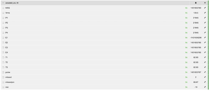
There is nothing connected, but I still find the values it is getting very strange???

OK, so I powered up node ID 16 and it reports similar data as shown in previous post… (again no claps connected, so I would expect “0”)

The emonPi is powered by the AC adapter only, maybe this is the issue?

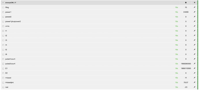
I then powered up the node ID 17 (for which I compiled the FW and only changed it node ID value)… I tried to power it with USB, and it returns different values… not sure they are good, but they are different…

Also the update speed is much slower than the two first emontx with the “default” firmware installed… My guess it that the update speed is about every 200 secs. where the others don’t get past 5 secs. in between updates. My guess is that the default .ino file is different to the default FW?

Just so we are clear, I did a git clone from within PlatformIO, then opened the platformio.ini file inside the folder EMOMTX34_CM. Then opened the emonTx34_CM.ino file and changed the “byte nodeID = 16;” (it then verified that it got node ID 17… (the physical switch on the board is set to 16… (kinda confusing), but verified the node ID from the serial console…

Now that I look at the values, I can see a "int pulse_period = 100; " maybe that needs to be changed to a lower value…
I can also see some power stuff like "float assumedVrms = 240.0; " which I guess should be 220 for me?

UPDATE: I now understand that I need to add node 17 in the emonhub.conf file… so it matches the two others… but doing that gave me the same garbage readings as the other two… maybe the config is broken some how?
UPDATE2: I of cause ended up searching this great forum, and found that setting “whitening = 0” in the emonhub.conf gave me the correct values from the emontx… not sure why it puts this in?

Yes. As you have no other Emon devices (correct?) then take a look in your emonhub.conf file and see if you have anything for an emonTx3. If you have 3 or more definition blocks with different Node IDs, then you use the third for your 3rd emonTx V3. If you haven’t, you will need to copy the existing block for the emonTx V3 and give it an unique Node ID - probably by deleting the block for something you don’t have and ‘stealing’ the ID. If you can connect a serial terminal program on your Mac either directly to the emonTx V3 or via the emonPi, then you can change the Node ID of the third emonTx V3 in EEPROM, and save it. The instructions are here: Configuration — OpenEnergyMonitor 0.0.1 documentation

I warned you that there had been changes - I think I read that someone else found this didn’t work.

I think I’ve answered this above before I read this far. As I wrote the EEPROM library, it will remain in EEPROM while you load “consistent” sketches, i.e. with identical use of the EEPROM. If you load a skech that uses it differently, it is erased. Again, all this might have been changed.

Don’t you mean the 5 V d.c? You only need the a.c. adapter on the emonPi if you are measuring power with it. If you’re not using one or both c.t’s, you don’t need it.

Do you mean the time between new values appearing in emonCMS. This can be set either in the sketch, or via the serial interface (if can be got working). If your sketch is this one https://github.com/openenergymonitor/emontx3/tree/master/firmware/emonTx34/emonTx34_CM
then you need to check that line 120 is:

 float period = 9.85;                                     // datalogging period - should be fractionally less than the PHPFINA database period in emonCMS

Looking at the changed code, it appears the “+++” unlock code has been disabled (but not removed) - you simply enter the commands. Unfortunately, without the ability to lock the serial input, it is possible to change the configuration and calibration by accident.

I can’t help you with Platfromio. It screwed my system up totally, so I refuse to have it on my machine.

This applies to pulse counting. Are you using the pulse input? If not, it does not affect you.

This is the voltage it uses to estimate apparent power when you don’t have the a.c. adapter.

Correct. The Node Definition is how emonHub knows how to convert a string of byte values

5 145 0 149 0 38 1 250 92 0 0 0 0 0 0 0 0 0 0 0 0 29 162 71 0 0 0 0 0 248 75 71 0 75 152 73 0

(those values are in decimal) into integers - 16 or 32-bit, signed or unsigned, to pass on to emonCMS.
You must have a valid Node ID definition for each (in your case) emonTx V3. There’s also one for the emonPi itself - Node 5.

Thank you :+1:

“Whitening” is a kind of encoding that prevents a long string of zero values being transmitted when using JeeeLib (otherwise, the receiver loses lock and fails). It’s not needed with LPL, which encrypts the message and so avoids the problem in a different but similar way.

Is everything looking better now? If I’ve missed explaining any points, remind me - but I’m not likely to be able to answer for a couple of days.

Hi Robert, yes it looks much better. The node ID 17 i compiled my self has the correct “period” set, but I still see that the values “goes into the red”… over 90 secs. but not always…this is temporally powered by USB, but seems a bit strange… but I can get on with the setup now :slight_smile:
Thanks for your great help as always.
Quick update: Node ID 16 is also having some “pauses” in its updates… Is it normal that the emontx is taking a break some times? Or is it maybe because right now they are all stacked on top of each other… with an RSSI of -24 to -26… I hope this is the cause…
(PS: If I want to connect it via USB, do I need a USB to serial converter to do that, or is it possible to just connect the USB port directly to the emonpi?)

Most likely, this is two emonTx’s trying to transmit at the same instant, and jamming each other - or something else on the same frequency.

You will need three serial to USB adapters, as I wrote earlier: