I concur, emonCMS or indeed one of the many other systems (that I’m not familiar with).
I have the code to report frequency, and the correction to energy accumulation appears to work (telling it I’d moved into the 60 Hz world stretched the reporting interval by the correct amount, but the energy accumulated at exactly the same rate).
Given that energy accumulation is now accurate (it wasn’t necessary in Robin’s Mk2PVRouter from which the library is derived), frequency is much more likely to be useful and meaningful to most users. So I think reporting the actual period won’t help. And rounding/truncation errors are carried forward anyway. What if the duration got lost in transmission? At least sending the accumulated value means that only the intervening value is lost, not the accumulation.
Note that emonCMS can handle the (external) accumulator being reset, it continues accumulating.
As per above, I plan to use emonCMS. I will now start to have a look at how than can be done.
Can I help test this before you release it? I can measure the frequency of my system accurately and there are whr meters on the PV output and house supply.
I think the match between the “official” values and the recording shows a very good correlation - it might have been better had I been using a shorter reporting period. The analogue quantities - voltage and current - and everything derived from them is subject to component tolerances, which is why the library has the facility to be calibrated by you if you have the instrumentation to do so.
There is no real need to update any installation using this library unless you experience large swings in the a.c. line frequency. The previous versions used mains time to calculate the energy over the reporting period: if the frequency is markedly different from the nominal value, this would lead to a corresponding error in the energy value reported. The energy calculation has been changed to use the processor clock, which removes that error. Note that the reporting interval itself is still timed using the mains clock.
The average mains frequency is now available as one of the values reported.
Note for developers: The library can now switch the ADC reference source. Details are included in the documentation. Users of the emonTx, emonPi and Arduino should not experiment with this, as damage to the processor is possible if the wrong setting is used.
I’m not sure I understand this, Robert. Does this mean the data is transmitted at slightly varying intervals? If so and if it is recorded in a PHPFina series, doesn’t that assume a constant time interval and won’t any power calculations derived from it therefore be inaccurate? (and perhaps even if a PHPTimeSeries file is used, it will also suffer unless an accurate timestamp is transmitted?). Or perhaps I’m misunderstanding?
Just to confirm, is this the average over the sample period? i.e. effectively a near instantaneous measurement of the frequency for normal logging purposes. It’s not a long-term average of some kind?
Yes, depending on the stability of your mains supply frequency - like it says. I’m not sure how else I can word it.
Is the explanation in the documentation not clear? Again, I’m not sure how else I can word it.
I did ask you to elaborate on what exactly you mean earlier by
and you didn’t respond then, now you’re invoking “a PHPFina series” and you’re still saying that
I’m an engineer by training and I live in the real world. Nothing, unless you’re a bean-counter counting beans, can be absolutely accurate, especially when it involves physical quantities and the analogue world. It’s a matter of making a balanced judgement and getting results with an accuracy that is “good enough” for the purpose in hand. Take your electricity meter: that has errors. If those errors lie within a specified band, that is deemed acceptable. You have to put up with that. The instrumentation that your meter is calibrated against also has errors. These will of necessity lie withing a much narrower band, but you have to put up with those as well. And so on until you come to international standards, and when those agree to a sufficiently high degree, that is deemed to be “correct”. Until somebody develops something better.
You need to specify exactly what your perceived inaccuracy is, where it arises and what you think can be done - preferably something that is practical - to reduce or eliminate it.
Sorry, what documentation are you referring to? I’m simply responding to what you posted in your message, which is what I assume everybody else will be reading and interpreting.
I didn’t respond because you later said
And I took that to mean the issue I have in mind, even though I know you were responding to Simon. So let me try to restate it.
If a count of mains cycles is used at any point in the calculation as a substitute for the actual time interval, there will be errors induced, because the mains cycles take differing amounts of time depending on the frequency. Emoncms, and especially PHPfina files, assume a linear timebase and have no means of adjusting sample times. In Simon’s case these errors can be up to 4% and should be avoidable.
I’m trying to understand whether all the data reported is derived from actual time or mains cycles. For example, if the mains is actually running at 52 Hz, does that mean that samples will be sent at 4.8 sec intervals instead of 5 sec intervals? And appoximately every thirty seconds, the emoncms file will miss a sample, overwriting it with the following one? If so, the deltas will look strange.
I simply don’t know the answer, so I’m asking the question.
I assume that anyone using the library will read the documentation that is bundled with it.
I don’t know all the inner details of emonCMS. @TrystanLea wrote it, and he’s the one who converted Robin’s software into the library. I have to assume that he thought it would be satisfactory.
There are two points here:
Firstly, the situation is, in reality, no different to the DS sketch with emonLib. In that, the reports are made at intervals that depend somewhere along the line on the time it takes to measure and process however many channels of data that are requested, as well as the sleep time between reports.
Secondly, the 4% error is exceptional, but not unexpected when the source is local generation. The UK legal limit is ±1% while the operational limit is 0.2 Hz (±0.4%). The European limit (as I understand it) is ±0.2 Hz, with a limit of 10 mHz before correction is applied. In the USA it is ±0.02 Hz. In mainland Australia, it is ±0.25 Hz.
I’m trying to determine if I’m exposed to this issue with my energy IC monitor. I set it to report energy values every 1000 half-cycles and that triggers a post through to emoncms, so my posting rate is roughly every 10 seconds as determined by the current grid frequency. The monitor’s cpu crystal is not involved; there are only two clocks involved: the grid, and the crystal on the machine running emoncms.
I think I’ve seen reference to feed “quality” but couldn’t immediately find it on a quick perusal of the emoncms webpages. Does anyone have any tips on how I can check if my grid induced jitter is messing up my feeds please?
I’m not the right person to answer his, however my perception is the mechanism is as follows:
Incoming data is dropped into a “slot” depending on its arrival time. While the drift between the sending clock and the receiving clock remains negligible (and of course the ideal starting situation is when the incoming data arrives exactly in the middle of its slot), all is well. If the drift is consistent in one direction - say the sending clock runs slow, the data will arrive late and eventually fall into the next slot, and there will be a null value recorded in the intended slot. I believe this is what feed quality is measuring. Alternatively, if the sending clock runs fast, data will arrive early and eventually catch up with a slot that already contains data. In that case, the previous data is overwritten and lost. I believe this was the strategy adopted for the default sketch that used emonLib, i.e. the time between samples was made shorter than the nominal 10 s (or 5 s) rate of the database clock. It was deemed less bad to overwrite a sample than to leave a null value.
Short of changing to the database that records the arrival time (maybe temporarily, because of the cost in data storage) and checking the time stamps individually, I don’t know of a way to do that. If it’s genuine jitter and not drift, you could be in a good situation and not lose any samples if the mean time of arrival falls on the midpoint of the slot, or a bad situation if the mean time falls on the slot boundary, in which case many samples will miss their slot and either leave null values or overwrite previous values.
I guess a possible solution would be to have a receiving clock phase locked to the arrival time of the data, so that the data always arrived near to the centre of the slot. It gets rather unwieldy with more than one data source, and the immediate question is how do you know what is the correct time to label the data with?
Another possible solution (as intimated only today in another thread) would be to poll the sensor node rather than have it free-running. That is a complete change of strategy that would be difficult to implement and maintain a degree of compatibility with the battery-powered emonTH, for example. And more so for emoncms.org.
Of course, if both ends use mains time and are on the same supply, the problem is jitter alone and phase locking, provided the jitter is less than half the reporting rate, is a complete solution.
I guess in the spirt of “leave no cycle unmeasured” that all argues for the front end accumulating energy locally and sending the current total to emoncms regularly. Then if things fall in the wrong timeslot it just means the consumption was recorded as occurring at the wrong time (slightly), but no consumption gets lost - which could start to add up.
Can someone tell me where I find the “quality” measurement for a feed please?
@Robert.Wall Thank you for providing this code. I’ve been using the non CM version of the library for many years and it has taught me a great deal about my power usage. So I am about to change out some appliances in my home, but before I do that, I wanted to upgrade my library to the CM version so I could get comparative results using the old appliances with the CM library.
I am using a Mega2560 because of the additional analog ports (A8-A16) and but I was only using A8-A10. When I take a reading from those analog ports using the CM, the values are off by about 8x, so I took a look at your library code and it looks like the second ADC is not being initialized at all (probably due to not even considering using it). If I extend the EmonLibCM_Start and EmonLibCM_Stop functions to include the ADCSR(b) ADC settings that you had initialized in the ADCSRA, I think it might work. It just seems that the settings are 8X larger that they should be. ADCSRA analog reading are dead on.
Why allow for 5 channels max? Is it to make sure we get enough samples for an accurate average?
Basically, yes and because it was written for the Atmel ATMega328P (it does actually say that in the documentation) and that has rather fewer analogue inputs than the Mega2560.
What you need to look at (I don’t know the '2560 and I’ve only thought about this for a few seconds) is the time for each ADC conversion - you may be able to improve that by restricting the width - and running both ADCs in parallel (of course, the '328P has only one) but for that you must create a second ISR to handle the results and make them available to the main loop.
Actually, the 2560 doesn’t have a second ADC. I sometimes hear it referred to as a “more powerful” Adruino, but for as far as compute power and ADC performance the two are identical. They run the same AVR core at the same clock speeds, and use the same lone ADC. What the 2560 does offer is more pins, a wider analog mux in front of the lone ADC and more flash and ram.
So you can write bigger programs, and declare bigger C arrays, and sample more analog pins… in that sense I guess you could say it’s more powerful, but in terms of ADC performance and V*I maths performance, the two processors are the same. Total sampling rate is identical, so introducing more channels means the sampling rate per channel will be proportionally reduced.
@dBC Thanks for clarifying that, I’d taken Joe’s statement at face value.
@rcojoe
On that basis, I don’t think its feasible to extend the number of channels being monitored beyond 6 (5 current, 1 voltage, giving roughly 32 samples per cycle per channel - 15th harmonic for us but even less for you in the USA) because the number of samples per cycle will reduce to the point where the bandwidth suffers and aliasing - unless effective anti-aliasing filters are incorporated into the hardware - will become a problem.
I think you should stop and do some basic maths to decide how many samples per cycle you need, if you can control the ADC resolution then what bit depth you need there (because there’s a speed trade-off to be had), and that will give you the maximum number of channels you can ‘simultaneously’ monitor.
Thank you @dBC and @Robert.Wall. I looked at the ADC for the 2650 last night and I couldn’t find any differences in the ADC so it must be the same ADC. I should only be sampling the pins that need to be sampled by the way I initialized the emonlibcm, keeping my pin count to the 5. 1,2,8,9,10. My readings on 8,9,10 are not as expected like they are on pins 1,2. So I may have to do some pin swapping to see if the odd readings are related to the higher pinset or related to my hardware. I am using the exact same configuration # and phase offset as I did in the original library, and my first two inputs on 1 and 2 are reading correctly. I’ll give it another try tonight.
OK, when I said the ADCs were identical but for a wider mux I was over-simplifying things a bit. The core of the ADC (and hence its performance) is identical, but sitting in front of it is not only a wider mux but also some op-amps allowing differential inputs and 10x and 200x amplification.
If I’m looking at the right code, it does this…
static byte ADC_Sequence[max_no_of_channels+1] = {0,1,2,3,4,5};        // <-- Sequence in which the analogue ports are scanned, first is Voltage, remainder are currents
...
ADMUX = 0x40 + ADC_Sequence[next];       // set up the next-but-one conversion
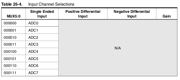
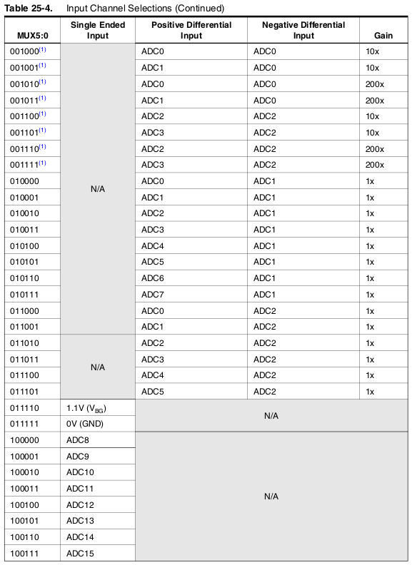
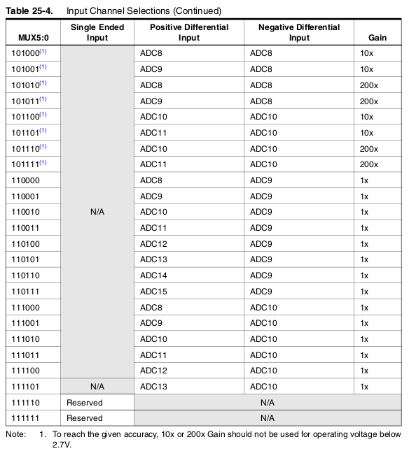
The datasheet reveals why you can’t just replace those numbers with 8,9,10. A setting of ‘8’ there will get you ADC0 with a 10x gain. A setting of ‘9’ will get you (ADC1 - ADC0)x10 and a setting of ‘10’ will get you ADC0x200. You’ll need to do some simple maths on the channel number first. For channels 8 and above you need to set MUX5 and it lives in a different register (ADCSRB). Check out how analogRead() in the standard Arduino libraries converts channel numbers into register writes and mimic that.
@dBC Yes! That’s the answer to the question I didn’t know to ask!! I did see the same tables in the datasheet and noticed the the MSB was 1 when querying the 8+ pins. It was late and I was trying to figure out where the library was querying the ADC for each pin, which I had not fully comprehended yet. So MUX5 32,33,34 = physical pins 8,9,10. lets see how that goes. Thank you so much for taking the time to laying it out. You saved me a ton of research time (even though I do like that part too cheers).