Emon lib - Theoretical + practical questions regarding capacitive voltage sensing

Good morning everybody,

I’ve gone and done something that I probably should have published, since it worked so darned well, and that is, two current transformers on a US split phase system, summed in “hardware” , properly burdened and going straight in to an ESP8266’s analog input, and posting directly to my emonPi. It worked fabulously for about 3 years now, with the only thing being my squirreley implementation of wifi on-boarding and setup, but that’s another problem easily solved by today’s great libraries.

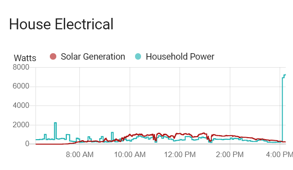
So here’s my issue now. I’ve added solar, so I need voltage sensing to tell which direction the power is flowing! Simple? Well the ESP only has one analog input. Sure, I could multiplex it and voltage divide a transformer, etc etc, but that needs more chips, etc, and also requires more tapping in to my box and live conductors. So here’s an idea…

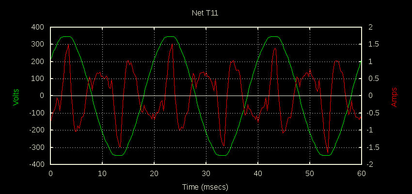
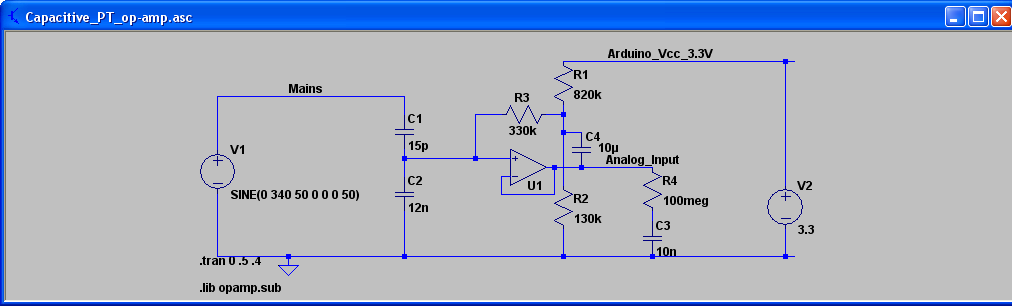
Capacitively couple a GPIO to the AC line to sense the voltage, only for the purpose of determining the direction of flow of power.

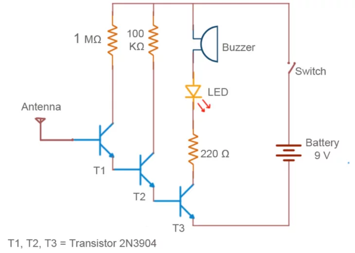
This is one of dozens of circuits on the interwebs, and this could easily be adapted to use on a micro-controller.

Obviously, I won’t have any of the fancy real power, apparent power, power factor, and actual voltage sensing readings, but I WOULD have a non-contact way to measure the voltage. The idea is that I can read the GPIO that the detection circuit is on, and if it’s high (because naturally, it’s only going to turn on when the polarity is one certain way) then it’s considered in phase, and current is flowing in one direction. If it’s anti-phase, then it’s obviously flowing the other direction.

The whole idea of just wrapping a little insulated “antenna” wire around the input to the power supply makes me giddy.

What do other people think about this?

I think the only reliable way to determine power direction is to sample a bunch of V*I readings, add them up and see if the result is positive or negative. In the attached capture, the Red signal is the output of my whole-house CT. Without doing the maths, it’s kinda hard to tell whether the result would come out positive or negative.

If you only have high power heating loads, where you know the power factor is close to 1 (and the grid isn’t normally too far off that either) then I think your idea stands something of a chance of working. But in the real world, then I’m with @dBC - you could very easily get false information.

Looking at it realistically, is it worth putting effort into building that when, for not a lot more effort and cost, you can do it properly and get trustworthy data?

1 Like

dBC -

Yes, I see what you’re saying. On the other hand, I’m doing the “current only” implementation of emonlib right now… with current clamps on my house, and although I haven’t looked at the waveforms of the whole house with my scope, on the bench the CTs were putting out waveforms that were a lot more sine-like, and in the current-only implementation, I get results that, while not revenue-grade, seem to be within a couple percent of what the meter is reporting. My mileage appears to be varying…

So here’s another interesting idea…

Since we can more or less detect where the zero crossings are, what if we synthesized a sine wave that’s in phase with what we’re picking up on the digital input and then took “measurements” off that sine wave. Remember, the goal here is non-contact voltage sensing.

We’re more or less detecting the zero crossings here (and I’m cheating because I’m taking readings every 16.3 ms plus the overhead for serial printing, so I’m actually sampling a whole lot of different waves but whatever)

Another surprising thing I checked is the power factor of the electric car chargers - 0.99 which I’d say is surprising, but not surprising. Think of how pissed the power company would be if they didn’t correct them!

Is it? - I thought, from what you wrote first, that it was one ADC and no multiplexing.

If you only want non-contact voltage sensing, then that’s not all that hard to do properly - it’s done in high voltage switchgear (66 kV up) and the basic idea is a capacitive divider. In your case the “top” capacitor is foil wrapped around one of the line conductors, and the “bottom” capacitor is a much larger value to earth. You need a very high input impedance amplifier to make use of the voltage.

I posted this ages ago on the old forum - if you search there you should find a few threads.

(V1 is your mains, C1 is the foil wrapped around the conductor.)

Right - Well, yes, more like I suppose, the PROBLEM was one ADC and not wanting to multiplex. And a nice side effect is non-contact, which is quite motivating in and of itself.

Also, I like that capacitive divider of yours.

But my motivations, whatever they are, aren’t exactly important for the question I have in my mind, and let’s just assume power factor is 0.99999

So at the moment, factually, I’m happy with the .calcIrms method as is basically shown in the example code. It’s giving me results I like. However, when I’m dumping 1 kw of power BACK to the grid, it shows that I’m USING 1KW, which makes perfect sense and it’s working properly.

You see what’s going on here - image

But the idea is that in the current only sampling code, I put a digital read in there, and sum the filteredI value in to a new variable IF the digital input is high. (Yeah, obviously it won’t nail the zero crossing because of parasitic capacitance, but it’s a qualitative measurement) and if that resultant number is positive then we leave the output alone, and if it’s negative, we multiply Irms by -1.

Admittedly, there will probably be some squirreleyness in very low current situations, but how bad they will be will have to be determined experimentally.

I’m actually messing around on the bench a little - I don’t have access to my current clamps at the moment, but even wrapping a piece of solid wire out of a piece of CAT5 around a single extension cord lead gives me a read on a sine wave, directly in to the Arduino GPIO and ADC too, which as was shown above, and it looks reasonable.

I’m going to give this a try - No harm in that anyway, and let everybody know how it works. Yeah, it’s imperfect, but it could be a “good enough” solution.

Actually, in thinking about this whole parasitic capacitance and nailing the zero crossing, I suppose I could probably sum filteredI in to different variables on both high and low states of the digital input, while testing a nice big heater coil, and figure out a calibration offset, since in real terms, they ought to be equal to each other in absolute value.

You can still square off the op.amp output from my circuit and use that as your digital input. If you make a voltage divider out of a small capacitor (the “aerial” as the diagram you posted erroneously refers to it) and an unknown and most likely non-linear impedance of the ADC input, then you’ve got to expect an unknown phase shift.

1 Like