Following the various threads on ASHP tweaking and I’m conscious that I’m very near the bottom of the rankings at https://heatpumpmonitor.org/.
One issue I suspect I have is the flow rate between my HP and the buffer tank. The pump is running flat out / maximum speed setting and I’m getting 1.25m3/h according to the Sontex heat meter.
The spec. for my 14kW unit is 17.9 l/min to 40.1 l/min so mine is right at the bottom of that - 20.83 l/min by my calculation.
Tempted to get a better / more capable pump and see what happens as flow rate seems to be rather important.
I’ve been looking over your heat pump stats for a while, and noticed that it was under performing. However, I don’t think this is directly connected to the flow speed - my own 11 kW unit is even closer to the bottom spec, but has reasonable performance.
What I have been wondering is if having two zones is hurting performance. Looking at the power charts, I think I can see moments when one of the zones opens or closes, and the COP changes dramatically when that happens. Performance is better when both are open.
Can you describe how these zones are controlled? Can you configure them to be open together for longer? For instance, raise the thermostat temperatures, and rely on weather compensation instead (see below).
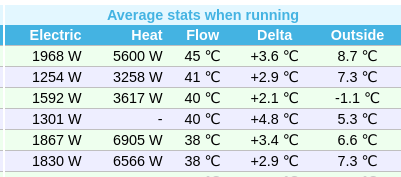
Your system also has the highest average flow temperature when running for last 30 days, at 45 ℃.
I would suggest knocking the weather compensation curve down by quite a bit, like maybe -5C, see if that helps too. If you get the balance just right, the heat pump will put the right amount of heat into the property, and you won’t need zone controls at all.
Yes, there are two zones but they run under auto-adaptation i.e. Mitsubishi’s own system which apparently uses some sort of smart learning type stuff. I really need indoor temperature ‘knowledge’ as I can get a lot of solar gain etc.
The house is entirely (all new) radiator based, around 25 in total and roughly split evenly between the two floors. All the emitters have TRVs other than those where the Mitsubishi remote wireless sensors live.
The plumbing/wiring is the ‘simple’ two zone system as described in the FTC6 manual i.e. same flow temperature to both rather than the more complicated version that uses more temp and flow sensors plus a mixer valve.
The programming is basically 20C in both zones from 6am to 8pm (up)/11pm(down) with the setback to 18C/19C. Weekends similar but with 21C downstairs and 20C upstairs.
The system volume is quite large and has a buffer tank/two pumps. The drop in flow temp you see is when the ‘cold’ water in the just opened zone hits the system. I monitor the CH flows and common return temperatures and they correspond.
TBH I find it keeps the house perfectly warm even when the outside temperature is below zero. Just not that efficient in terms of COP compared to others! The delta T in the ASHP flow and return temps seems to be smaller than optimal but now I’m unsure. Both pumps are Wilo Para SC - the CH one has a 9m head, the HP one a 6m head. All the HP plumbing is 28mm, CH a combination of 28/22/15.
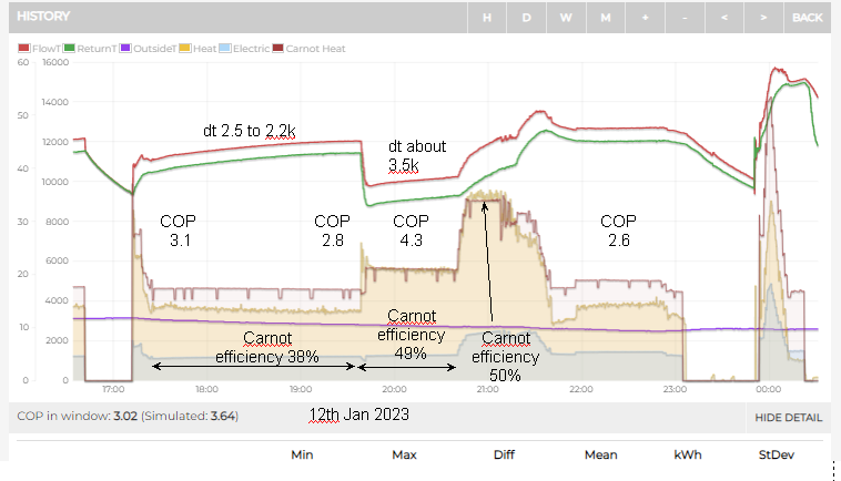
This was from January 11th, though the pattern can be seen quite easily on any day.
Some oft-repeated advice is to have all TRVs as open as possible, only using them to prevent rooms overheating in sunny days. This ensures that the emitters can output all of the heat being provided by the heat pump.
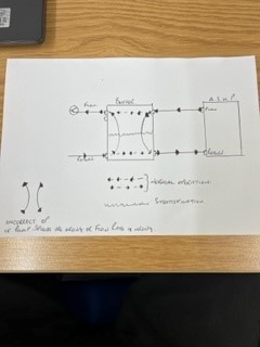
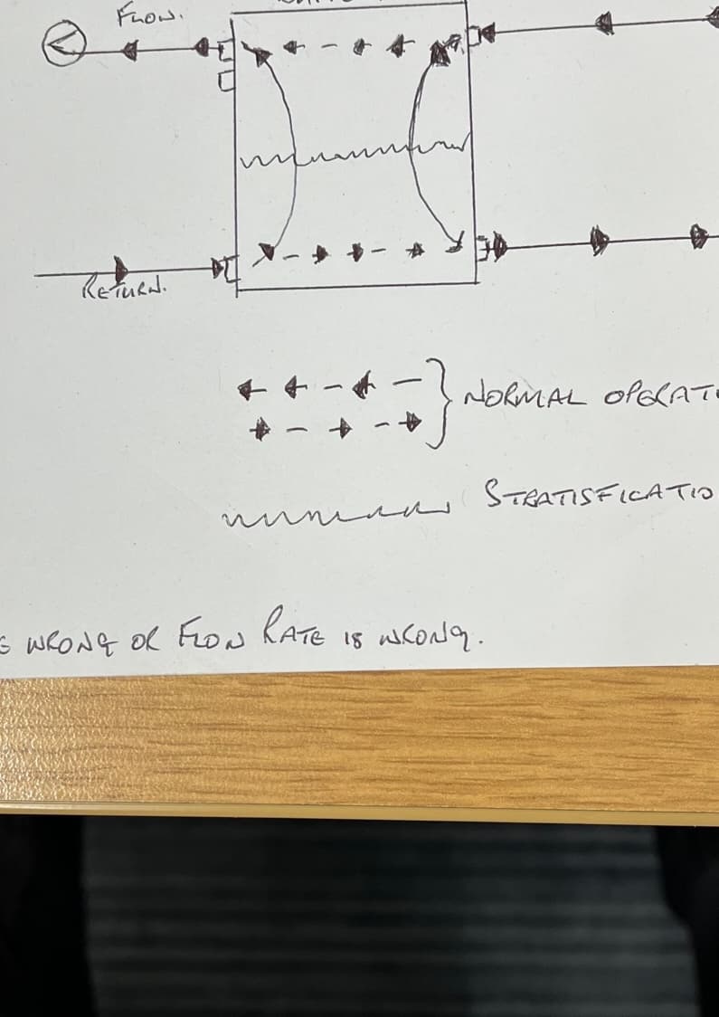
How is the buffer tank plumbed in? Is it in series (adding volume) or in parallel (providing hydraulic separation). I’d have thought that 25 radiators was more than enough volume (but I’m no heating engineer).
I think the first step is to get that flow temperature down. I don’t know how to do that with auto-adapt…
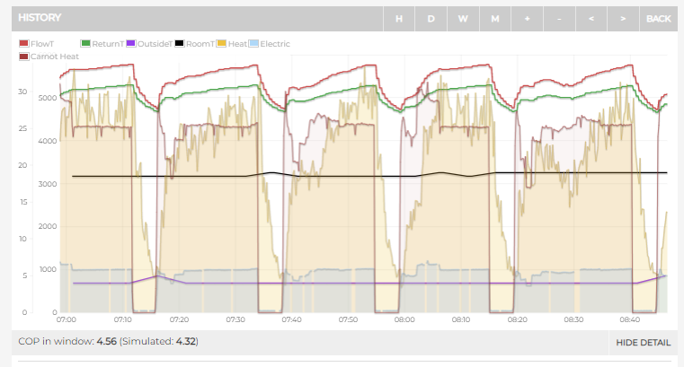
Using Trystan’s Carnot COP facility, the carnot cop when the dt is around 3.5 is about right at 49% (at 20:00), but where flow temp is edging up to 45, and the compressor slow, the Carnot efficiency seems to be down at 38%… it should be around 49%. The dt is close. Could this actually be in-part be a sensor issue? Accuracy of heat meters is gets worse as dt gets close. during the no-heat period at 17:00, the two readings seem to come together as they should. So… why should the COP be so low when power is low and dt is close?
As an experiment, can you actually slow the flow down so that the dt rises to about 3.5 and 5 respectively (instead of 2.3 and 3.5ish).
So, I’m not sure why your COP seems low at these conditions, but Ecoforest show a graph of their unit with significantly lower COP at low power, but the Mitsubishi DataBook shows a similar COP across the range from maximum to minimum speed…
As Tim says, it would be nice to work towards getting your flow temperature down.
What temperure is the water entering your heat emitters? Is there much ‘drop’ in temperature from ASHP flow temp. ,and the flow into radiators? More importantly, what is the mean rad temperature? It would be nice to know what the return temperature is for every rad. IF some rads have TRVs ‘throttling’ the flow ( e.g. flow-return dt at rad is high, the some Rads must be returning quite low return temperatures to the buffer, and this low temperature is not getting back to your heat pump. I’m guessing the flow-rate around the radiators is much slower than the flow in the heat pump, and that there is a significant net downward flow in your buffer tank… not ideal. We need a pipe schematic.
Lots of aspects to consider here.
ideally, you would have sensors on the flow and return out of buffer tank to radiators.
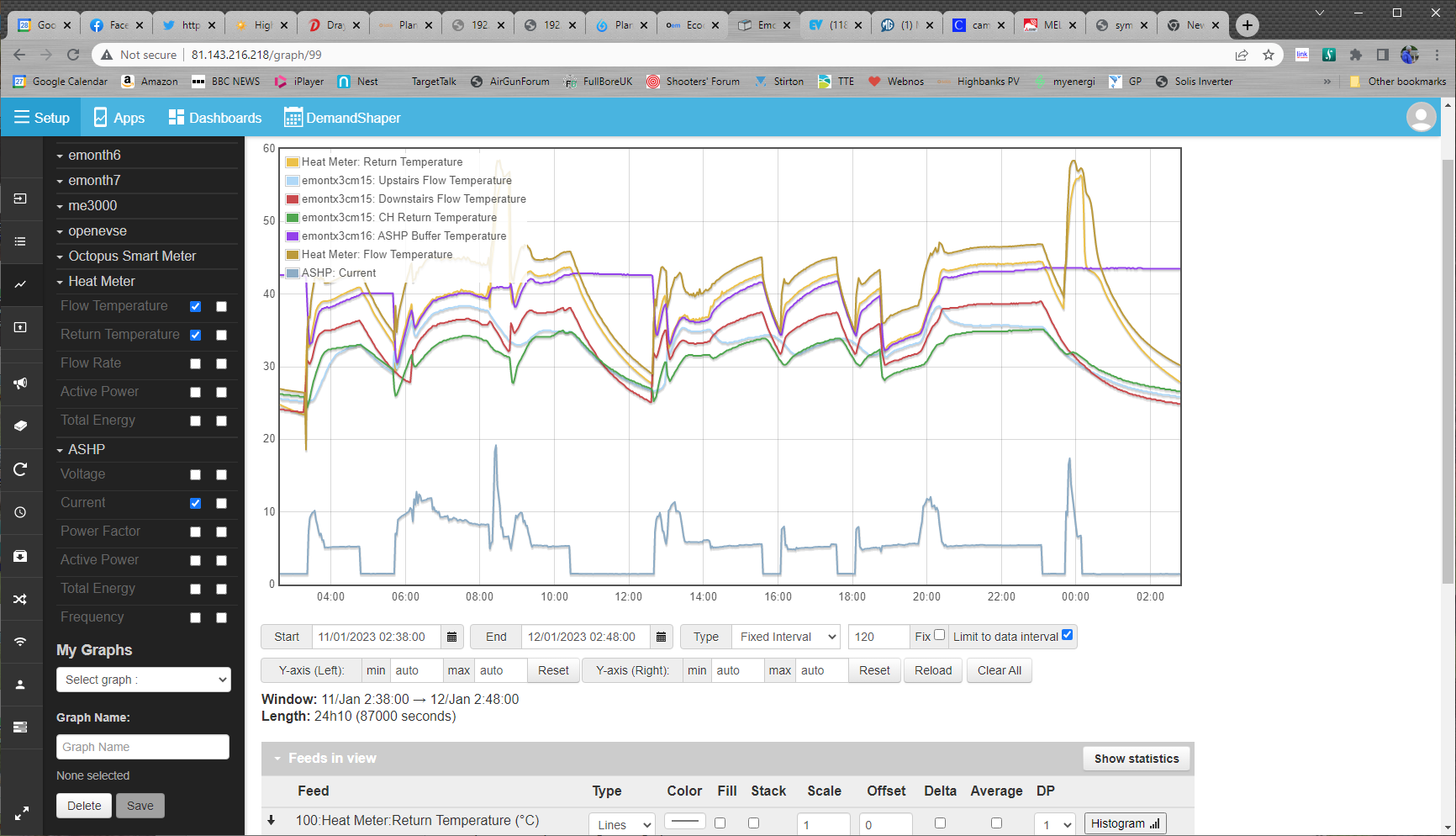
Why is the return temperature on the graph wobbly (the green from 20:30 inwards) Generally, the return from the buffer or rads should be steady. I have seen a wobbly flow temp when the COP is lower than expected, and I think this is a bit of a refrigerant issue… liquid refrigerant entering the compressor. I have not seen wobbly return temp. Is there a flow-return bypass on your system?
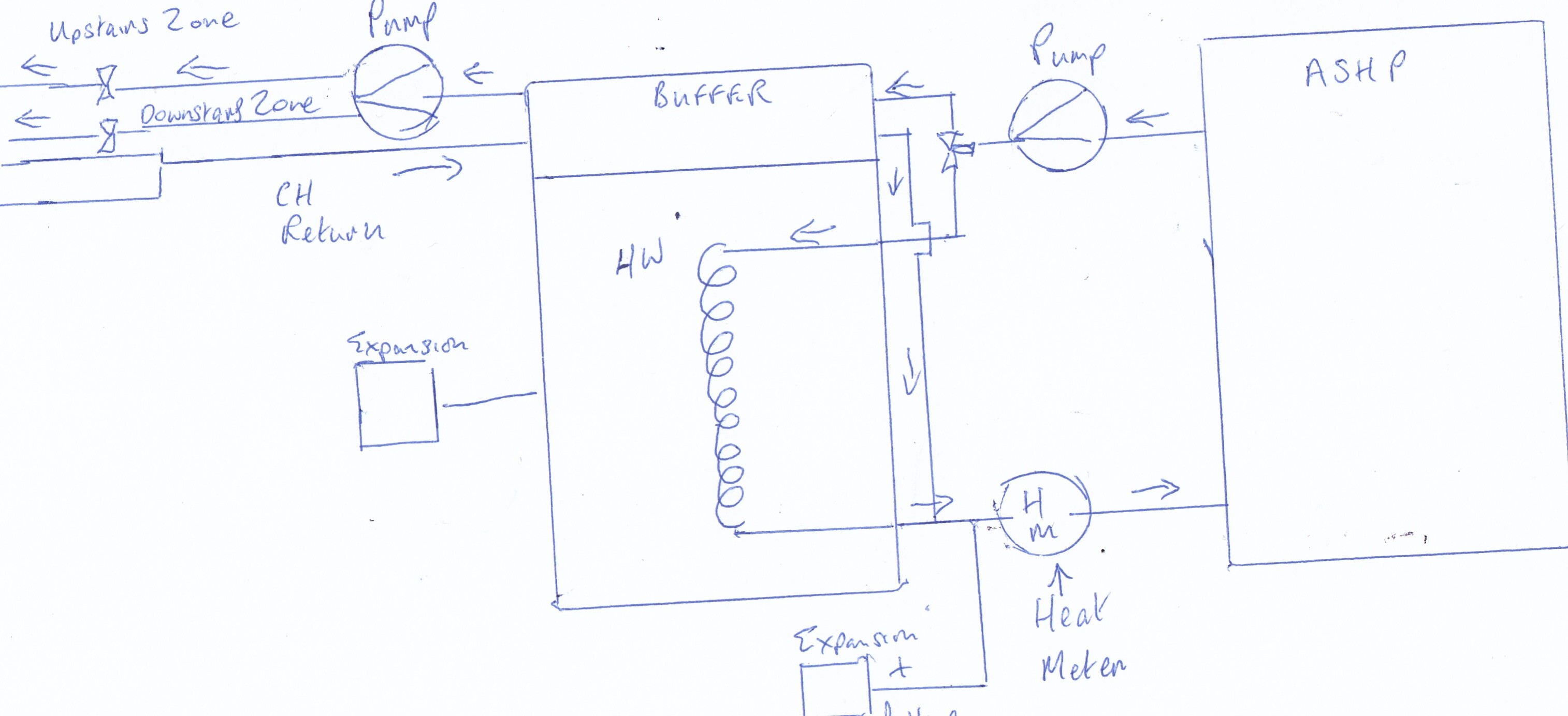
The system is essentially plumbed with the CH on one side of the buffer tank - one pump and two zone valves for which I monitor the temperatures (using a tx3) of each zone flow and the return into the tank. The other side is the ASHP with a circulation pump, filter, heat meter and valve to control heat into either the buffer tank or the DHW coil. I try and draw a schematic tomorrow. I also have the temp of the buffer tank measured.
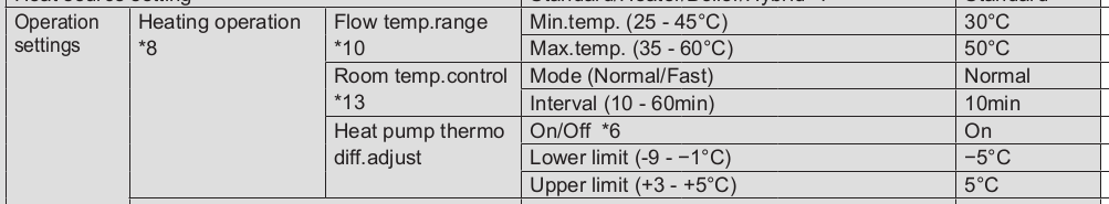
Referring to the FTC6 manual and the settings mentioned, some don’t have effect when auto adaptation is on but I’ll double check. I believe my max temp is set to 45 but is clearly higher
No idea about the wobbly line; the heat meter sends data every 10s but I think emoncms posts it out at a longer interval from memory. I’ll try and get an overlay graph of the day in question on my local emoncms with all the temps shown and post here. In the meantime, I’ll turn the HP circulation pump down from III to II to see what happens. The CH pump has more head but also probably a lot more resistance; don’t have a flow meter on that but may add one I guess on the common return as that’s accessible and would be easy to do I think.
Re flow rate out of buffer tank… given the average kW in must equal average kW out to rads, you should be able estimate the flowrate to radiators using simple proportion of dt.
I was looking again at a recent section. After stopping, the pump keeps running, and the dt decays over the 5min ‘off’ period. the ‘coming together’ of flow and return seems surprisingly slow. Even after 5 mins off, there is still 1k dt. How long are your pipe runs and where is the heat meter? After starting, there is an immediate response in flow and return, but the heat output takes a while to build up. Also interesting to note that at 8:30 there is a dip in heat output at a time where the input is steady
I observed this behaviour on my 6kW unit. I think its a refrigerant control issue, but not yet had any answers from Mitsubishi. There is a sensor inside the unit on the discharge pipe (TH4) from the compressor. This can be accessed on the Ecodan ‘running information’ code 004. I expect that at 08:30 and after 07:40, the discharge superheat was very low or zero. I have fitted a ds18b20 to the discharge pipe, and observe occasional ‘crash’ of COP correlating with low discharge temperature. Can you do the same? I’m not sure if its a big problem since the Carnot COP overlay shows that you are exceeding expected COP for much of the time.
Could spend hours pondering these graphs!
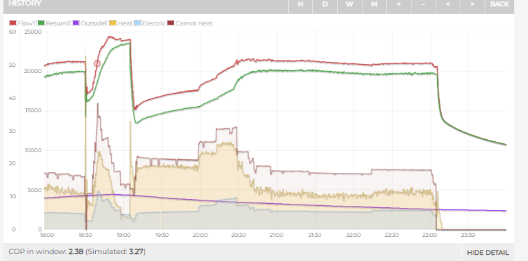
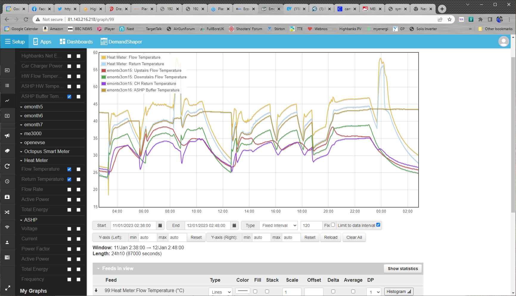
I’ve uploaded below two graphs showing the same thing but one also has the ASHP current on to indicate how hard it is working (or not). The date/times match the graph posted above. Note that all my data is also publicly available on emoncms.org I think.
The HP is just outside the wall where the cylinder/buffer is so the run isn’t very long. The heatmeter is just on the inside of the wall where the return to the HP goes through.
I can look at sticking a temp probe in the unit to measure TH4 - I’ve spare inputs on my tx4. Or I could repurpose a TH unit I have near there instead.
I’ve switched the circulation pump for the ASHP side down to II and altered the flow temps above to 25/45. The room temp control values are ignored when ‘advanced auto adaptation’ is on, which I have and I’ve zero idea what heat pump thermo diff adjust does other than it’s on by default - I haven’t changed the values.
Sunny here today so the HP won’t kick in until late afternoon I expect.
How large is that buffer in litres and how far apart are the tappings for flow and return, there is a possibility that your buffer is having a negative effect on your system with your heatpump pump just circulating around the flow and return and the same effect on the circuit side. i will draw and upload a pic illustrating what i mean. if you have only 1 pump on the zone side this will effect your flow rates dramatically if you have 1 or 2 zones open.
Hadn’t thought about only having one pump; the wiring is there essentially but I’d need to do some plumbing to get another in - not impossible though. I’m planning on fitting a pressure sensor and maybe a flow meter or two as well when the weather warms up so an additional pump could be done at the same time. If I’m organised and plan appropriately, I can switch from the ‘simple’ two zone to the ‘complicated’ one.
At a rough estimate I’m getting about 20 l/m on the CH side. Difficult to be exact because of the one pump/two zone scenario. Generally if it’s only heating one zone then it’s downstairs but solar gain can nix that and the upstairs zone sometimes is solo.
I think Mike is right about recirc in the buffer. Looking at your graph temperatures, its surprising how bad it is. It is also the only way of explaining how the return to HP rises very soon after start. Its got 1" bsp fittings, so it might be possible to fit a 28mm copper extension to go inside the buffer to take the HP flow nearer to the flow to rads. Also maybe direct the rad return in the vicinity of the HP return. Given the odd angles around the cylinder… internal distribution pipe(s) might not be easy/practical. Converting to 3-pipe buffer could be an option?? Needs more thinking about. Its a good case to show before and after results, and the benefits of monitoring
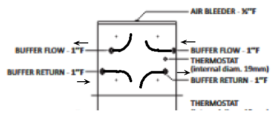
I think your Joules spec sheet above answers Mike’s question… the tapings are not far enough apart! Buffer tanks should be tall and thin, OR have decent baffle/spreader internals. My hunch is that the designers of these tanks consider water flow inside, but manufacturers remove them from the design to cut manufacturing costs… How many other buffers like this are out there?
It would not be too hard to add some 28mm copper to the 1"bsp fittings… A bit like shown here. Would be interesting to see if you could drop the HP flow considerable, and have same temperature radiators. Significant improvement in COP.
I’m planning to drain down at some point to make some changes and altering the buffer would be doable.
I’m fairly competent at plumbing - I guess I’ll have to lengthen the existing pipes to extend into the buffer assuming it’s a compression fitting and it doesn’t narrow into the tank.
Of the settings mentioned further back in the thread, the room responsiveness ones don’t have any effect as per the manual but the flow temp min and max does - I changed it from 30/50 to 25/45 and I’m not seeing flow over 45C now unless the DHW is heating. COP has gone up already and the house is still warm. I also reduced the ASHP side pump speed from III to II but the flow rate has remained the same!? Will turn it down to I now and see what happens. It seems the maximum flow is restricted elsewhere but all the pipework is 28mm and the flow meter is 1" as well. The is a Fernox magnetic thing in the circuit - I wonder if that’s the restriction.
If I’m draining down I’ll add a mixer valve and another CH pump and use the ‘intelligent’ 2-zone layout - all the relevant thermistors other than the buffer tank are already fitted but just don’t get used by the FTC6 controller in the current layout (i.e. two zone but same flow temp to each) - I’ll add the remaining one to the buffer and that might also improve things once implemented.
I would try your pump on the lowest setting because I think part of the issue is the amount of pipework you have from the heatpump to the buffer, that it is not large enough for your pump speed to have any effect. If you are going to do work I would consider running your primaries in 35mm upto the buffer if possible, this will increase your volume and flow rate, decrease your resistance and possibly any system noise too. It should also help with cycling problems and help with defrost cycles.