So I have my TX running for a couple days now, but it occurs to me that I’m not reading my heat pump correctly.
I have CT1 and CT2 on the incoming split phase lines to my house, CT3 is attached to my heat pump and I have the US 120v voltage sensor (wall wart). Heat pump is a 220v appliance though, so am I correct in assuming that the TX thinks it’s only 120 and I need to double the values I’m seeing to get a correct reading on the dashboard?
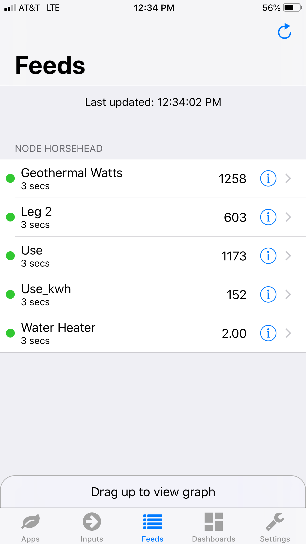
It’s telling me 700w while it’s running, I think 1400 would be nearer the mark.
Seeing the same low readings on my water heater, 220v heater so assuming same thing is going on.
As I suspected, thank you for confirming. Made the changes, now it looks more correct but there’s a new wrinkle- heat pump is now drawing more than the total power for the whole house. See the picture, I assume this is a calibration issue with CT1/CT2? I have the larger 019 ones there because my wire gauge was quite large, guessing I’ll have to do some more fine tuning with the sketch?
Which “019”? Are they all the same SCT-019-000 200 A : 33 mA ?
You don’t really need the larger 200 A c.t. on individual circuits where you have the smaller gauge wire. In general, you should have the c.t. with the lowest current rating that is higher than the maximum current you’ll see on that circuit.
Do you have a programmer? If so, the best place to adjust the calibration is in the sketch in the emonTx itself, rather than further down the chain. The nominal calibration constant to go in the sketch would be 275.48 (to replace the 90.9 for our 100 A : 50 mA c.t.) Those values are the nominal ones. They will be affected by the tolerances of the c.t’s themselves, the burden resistor and the voltage reference in the emonTx. If you have access to an accurate clamp ammeter, you could calibrate against that. By uncommenting some lines, you should see the currents reported in the serial monitor.
I’m afraid that without knowing the units, that doesn’t mean much.
I only have the SCT-019-000’s on my split phase input due to the diameter of the insulation on the wires, which are really fat for some reason. The standard blue CT’s didn’t fit around them. All the other CT’s are the smaller ones included in the kit though, those are the ones on my geothermal heat pump and hybrid water heater.
I’m have to play around with the sketch a bit, probably need to tweak the calibration. I’ll bounce it against another meter like you suggested.
That is a well-known problem for USA users. The SCT-013-000 is fine for the standard UK meter tails at 16 mm² or 25 mm². What wasn’t clear from your posts was which c.t. was being used for the heat pump and water heater.
@Robert.Wall
He’s got the 200 A CTs on his Service Entrance Wires (incomers)
@Nickolas_Williams,
Your Service Entrance Wires are large because as the main feed to your house, they must be able
to carry ~100 Amps. In addition to that, they are Aluminum, which means they need to be 2 AWG
(American Wire Gauge) sizes larger than the equivalent ampacity Copper wire. Houses built after
c.1970 use Aluminum Service Entrance Wires. The change from Copper to Aluminum was to
save money, i.e. Aluminum is costs less than Copper.
Bottom line? Their outside diameter is “standard fare” for 200 Amp US residential electrical service.