I see, while i do use the raspi, i manually installed it all, tho i may of installed the emonpi version, but thats an easy fix to reinstall the normal one
my emonHub conf simply has the inputs (serial usb as you do) and then the emonCMS output, i run emonCMS locally on that pi, as i have no real need to send it remotely and can still access the data if need be via the web and/or app (still to be tested) but ima just post the data to localhost instead of a remote server, but that’s nice to know! no MQTT requirement then keeps things simple
all bits and bobs have arrived now (quite fast! even the CTs) so ill be gin assembling it all soon
emonTx all changed to the resistor and also soldered the 3.5mm plugs to the CTs
I’ve now started looking at the sketch side of things… so from what I understand im going to take a measurement from each of the phases as if they were a single phase, all well and understood there. What I’m a little confused by is the phase bit… so I understand that i need to account for the phases, but i don’t quite understand it all… in most of the sketches I’ve seen they have a value of 1.7… this bit confuses me, what is 1.7? and how do i do it for each of the phases… i thought we have 360 degrees and divide that by 3 but I’m probably horribly wrong there…
Im going by the noRF Direct Sketch and modified it… so far I have the following with theoretical calibrations:
Sketch
    // EmonTx V3 Direct Serial example
    // AC-AC adapter must be used with this example (highly recomneded for more accurate Real Power calculations)
    // Useful for direct connection to Raspberry Pi or computer via USB to UART cable
    // Forum thread: http://openenergymonitor.org/emon/node/3872

    // Tell emonLib this is the emonTx V3
    // - don't read Vcc assume Vcc = 3.3V as is always the case on emonTx V3
    // - eliminates bandgap error and need for calibration http://harizanov.com/2013/09/thoughts-on-avr-adc-accuracy/
    #define emonTxV3

    // Include Emon Library
    #include "EmonLib.h"

    // Create four instances
    EnergyMonitor ct1;

    // Calibration valus!
    const float Vcal        = 268.97;     // Ideal Power 77DB-06-09 (UK Plug type) =  268.97
    const float Ical        = 192.31;     // 7500 turns / 39 Ohm burden resistor = 192.307
    const float Psft        = 1.7;        // Phase Shift...

    unsigned long lastpost    = 0;
    const byte LEDpin         = 6;        // emonTx V3 LED
    const int nodeID          = 10;       // node ID for emonHub

    void setup()
    {
      pinMode(LEDpin, OUTPUT);
      digitalWrite(LEDpin,HIGH);

      Serial.begin(9600);
      Serial.println("emonTx V3 Direct Serial (3 Phase - 1 Line)");

      // CT Voltage calibration
      // ADC pin, Vcal Calibration, phase_shift
      ct1.voltage(0, Vcal, Psft);

      // CT Current calibration
      ct1.current(1, Ical);

      lastpost = 0;

      delay(2000);
      digitalWrite(LEDpin,LOW);
    }

    void loop()
    {

      // A simple timer to fix the post rate to once every 10 seconds
      // Please dont post faster than once every 5 seconds to emoncms.org
      // Host your own local installation of emoncms for higher resolutions
      if ((millis()-lastpost)>=10000)
      {
        lastpost = millis();

        // .calcVI: Calculate all. No.of half wavelengths (crossings), time-out
        ct1.calcVI(20,2000);

        // Print to serial
        Serial.print(nodeID); Serial.print(' ');
        Serial.print(ct1.realPower); Serial.print(' ');
        Serial.println(ct1.Vrms); Serial.print(' ');
        Serial.println(ct1.Irms); Serial.print(' ');
        Serial.println(ct1.apparentPower);


        digitalWrite(LEDpin,HIGH);
        delay(200);
        digitalWrite(LEDpin,LOW);

        // Note: the following measurements are also available:
        // - ct1.apparentPower
        // - ct1.Vrms
        // - ct1.Irms
      }
    }
Also read something about timing of each emonTx measurement not being equal… is this a big problem? Wonder how to overcome this is need be?
I read through the emonLib and i get the gist or most of what is happening, the phase shift is the biggest one that is getting to me
Yes, you clearly are! Because you are using a single emonTx for each phase, while you are inside an emonTx, you can forget the other two phases. Each emonTx works as if it were on a single phase supply - because it is!
All you need to do is make sure its a.c. adapter is monitoring the same phase as its CTs.
The “1.7” value for phasecal.
This is found by experiment. What it does is correct for the phase and timing errors that you cannot avoid. How it does it is described in Resources > Building Blocks > Explanation of the phase correction algorithm. You can see what the transformer phase errors might be in the reports (also in Building Blocks) and the timing error comes from reading voltage and current one after the other, because we have only one ADC and cannot read them both at exactly the same instant. There is nothing you can do about that. If you do not have the CT and a.c adapter from the shop, 1.7 will not be the correct value.
You will have to expand on what you mean there, the individual adc reads are managed by emonlib, the phasecal can be calibrated or the reporting interval altered if needed.
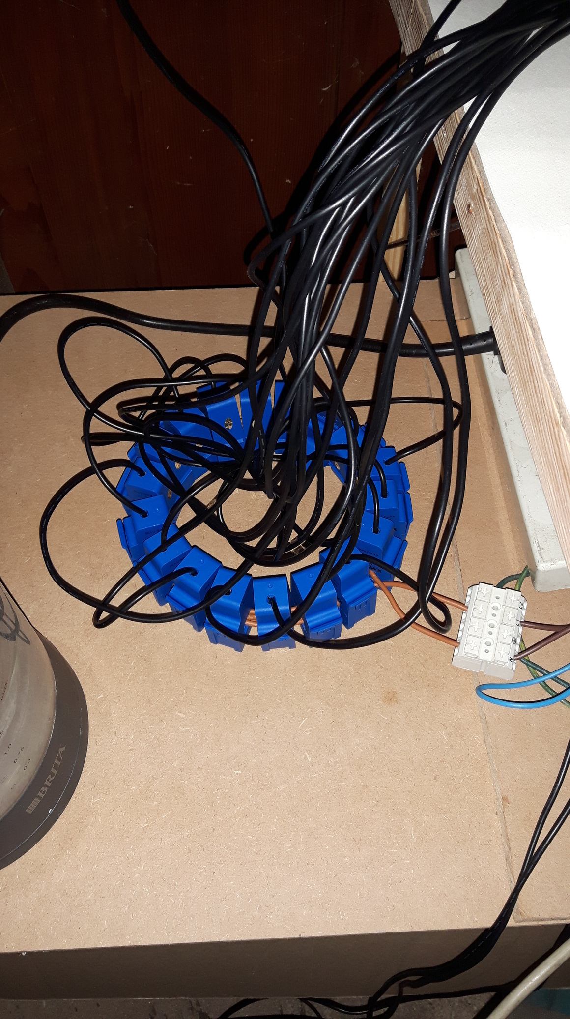
The 3 boards are phase agnostic, you can test each one on the same phase, if you look at my first pic I have all the AC:AC adapters plugged in to a 4way trailing extension lead and you can just about make out my test ring of CT’s on the floor below it (here’s a better pic)
This way you can test without any complications from attaching to wrong wires, in the wrong direction or phase etc, and then once installed you know any unusual results come from CT positioning alone.
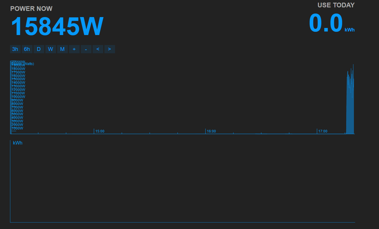
Nobody can answer that without knowing your system voltage, and the load. The maximum you might measure in the UK, with the shop CT, would be 24 kW, so that reading is plausible.
As per my previous post, there is value in hooking up all the CT’s and AC:AC adapters to one phase to confirm all is ok BEFORE installation and the complexity of multiple phases and different circuits confuse things.
Daft question Paul @pb66
How do you tell if its a genuine FTDI chip?
Reason is that I cant get any data to transfer.
I’ve moved the cables around in the following arrangement…
Black (GND)
Space (N/A)
Red (5v)
Green (TXD)
White (RXD)
Yellow (RTS)
Blue (CTS) (NOT CONNECTED)
I would recommend using an arduino IDE on a PC connected to the emonTx until you confirm good data coming out of the emonTx.
I see you are using baud 115200 is that correct? only the very latest emonTx sketches are 115200 and they are unlikely to have a serial output that works “out of the box” with emonhub.
I cannot confirm the wiring other than by the pinout on ebay which you seem to have tackled ok.
From the Arduino IDE serial console, if you have the rx and tx lines of your programmer shorted with a piece of wire or a paperclip etc you should see anything you type in the top box echoed in the main box at any baud as you are siply looping the tx back into the rx, this tests that the device is working and that you have the correct rx and tx lines.
Connecting it to the emonTx should then give you the emontx start-up text in the arduino ide serial console, if there’s gobbledy-gook being printed you have comms but the wrong baud.
If you have nothing, is the led flashing on the emonTx? that should confirm you have power.
It maybe easy to get the rx and tx lines around the wrong way as it is unclear from the pinout if they are labeling the devices pins or telling you what they should connect to on the other device (eg emonTx), obviously the rx of the FTDI goes to the emonTx tx pin and vice versa.
The data format you want to see is 10 123.45 123.45 123.45 123.45 etc ie starts with a node id and then each value is passed as a space separated human readable float value. You can have as many or as few values as you choose.
Once you have good data coming into the IDE and you have confirmed the baud you can move the FTDI usb to the emonPi and confidently set up the conf.
The above should apply to both all the FDTI’s and usb programmers (fake or otherwise) but to test if the device has a writable eeprom (ie genuine or a better class of fake) you should download the FTDI “FT_PROG” utility from their site and try writting to the eeprom, Just as quick test I usually read the device then just alter the product description slightly eg add an “X” or something and write it, the read it again to see if the edit stuck, if it didn’t it is probably a poor fake.
In serial comms (aka telephones) you normally connect the TX at one end to the RX at the other end, and vice versa. The only place I know of where that falls down is (perversely) the emon kit, where the changeover has been done for you on the PCB, i.e. the RX pin of the processor goes to the TX pin on the connector, then you connect the TX on the connector to the TX on wherever the data is coming from.
So if in doubt, the easy first step is to swap TX and RX
Thanks Paul @pb66, that utility worked and I was able to write too the chip to confirm that it has a EEPROM.
Yes the serial speed is 115200 as I’m using the latest sketch, I have plugged the lead into the laptop and setup a putty session and got the following printed every 10s…
ct1:0,ct2:1,ct3:0,ct4:0,vrms:23769,pulse:0,t0:77
Thanks Robert, TBH I copied the programmer that I originally bought from the shop.
OK, so I realise that the string isn’t formatted correctly so I have changed the sketch, when issuing a cat command on a SSH session I get …
root@emonpi(ro):~# cat /dev/ttyUSB0

11 1 4 1 0 23737 0 0:73

11 1 4 1 0 23731 0 0:73

11 2 4 2 0 23736 0 0:75

11 2 4 2 0 23740 0 0:73
Looking through the emonhub.log i get…
2016-12-17 22:30:48,752 WARNING  emoncmsorg send failure: wanted 'ok' but got ''
2016-12-17 22:30:48,761 INFO     emoncmsorg sending: 192.168.10.34/emoncms/myip/set.json?apikey=E-M-O-N-C-M-S-A-P-I-K-E-Y
2016-12-17 22:30:48,777 WARNING  emoncmsorg emoncmsorg couldn't send to server, Exception: Traceback (most recent call last):
  File "/home/pi/emonhub/src/interfacers/EmonHubEmoncmsHTTPInterfacer.py", line 123, in _send_post
    response = urllib2.urlopen(request, timeout=60)
  File "/usr/lib/python2.7/urllib2.py", line 154, in urlopen
    return opener.open(url, data, timeout)
  File "/usr/lib/python2.7/urllib2.py", line 423, in open
    protocol = req.get_type()
  File "/usr/lib/python2.7/urllib2.py", line 285, in get_type
    raise ValueError, "unknown url type: %s" % self.__original
ValueError: unknown url type: 192.168.10.34/emoncms/myip/set.json?apikey=xxxxxxxxxxxxxxxxxxxxxxxxxxxxxxxxxxxx

2016-12-17 22:30:48,894 WARNING  MainThread SerialArduino thread is dead
2016-12-17 22:30:49,243 WARNING  MainThread SerialArduino thread is dead
2016-12-17 22:30:49,665 WARNING  MainThread SerialArduino thread is dead
2016-12-17 22:30:50,067 WARNING  MainThread SerialArduino thread is dead
2016-12-17 22:30:50,416 WARNING  MainThread SerialArduino thread is dead
2016-12-17 22:30:50,764 WARNING  MainThread SerialArduino thread is dead
2016-12-17 22:30:51,114 WARNING  MainThread SerialArduino thread is dead
EmonHUB config is…
[[SerialArduino]]
   Type = EmonHubSerialInterfacer
    [[[init_settings]]]
         com_port = /dev/ttyUSB0
        com_baud = 115200                         # 9600 for old RFM12Pi
    [[[runtimesettings]]]
There is an issue with the “0:73” it’s not recognized as a numeric value.
But there is also another issue there, the myip url is poorly formed, there is no “http://” have you got myip setup on your local server?
and have you set up the correct full server url? eg http://192.168.10.34/emoncms/
Are you using http for sending to the local emoncms rather than MQTT?
2016-12-18 00:43:15,821 WARNING  MainThread SerialArduino thread is dead
2016-12-18 00:43:16,136 WARNING  MainThread SerialArduino thread is dead
2016-12-18 00:43:16,540 WARNING  MainThread SerialArduino thread is dead
2016-12-18 00:43:16,585 INFO     emoncmsorg sending: http://192.168.10.34/emoncms/input/bulk.json?apikey=E-M-O-N-C-M-S-A-P-I-K-E-Y&data=[]&sentat=1482021796
2016-12-18 00:43:16,618 WARNING  emoncmsorg send failure: wanted 'ok' but got 'Error: Format error, json string supplied is not valid
'
2016-12-18 00:43:16,858 WARNING  MainThread SerialArduino thread is dead
2016-12-18 00:43:17,175 WARNING  MainThread SerialArduino thread is dead
2016-12-18 00:43:17,495 WARNING  MainThread SerialArduino thread is dead
2016-12-18 00:43:17,811 WARNING  MainThread SerialArduino thread is dead
2016-12-18 00:43:18,127 WARNING  MainThread SerialArduino thread is dead
2016-12-18 00:43:18,490 WARNING  MainThread SerialArduino thread is dead
2016-12-18 00:43:18,807 WARNING  MainThread SerialArduino thread is dead
2016-12-18 00:43:19,126 WARNING  MainThread SerialArduino thread is dead
Further back in the logs leading up to the first “thread is dead” is where the clue’s will lie, but the packet isn’t formed correctly anyway, so you needn’t spend time hunting out the logs. I would fix the sketch and try again first.
PS - rather than using the html divs for posting a code block, try using
Try changing the serial print in the temp sensor code to
if (DS18B20_STATUS==1){
      for(byte j=0;j<numSensors;j++){
        Serial.print(" "); Serial.print(emontx.temp[j]);
      }
    }
The code was printing space followed by the temp sensor array index and then the temperture value imediatedly without a space eg temp sensor in position 0 has a value of 72 = 072.