Hi Everyone - My first post here.
Im a home powerwall builder here in NSW Australia. I have a 45kwh Nissan Leaf based powerwall in 14S21P configuration ~800ah.
I currently use Batrium BMS and am seriously considering making the switch to DIYBMS.
As I use Victron inverters and MPPT’s, I will need the new Victron integration and have a question or two and a feature suggestion regarding the Victron Integration (as requested by Stuart).
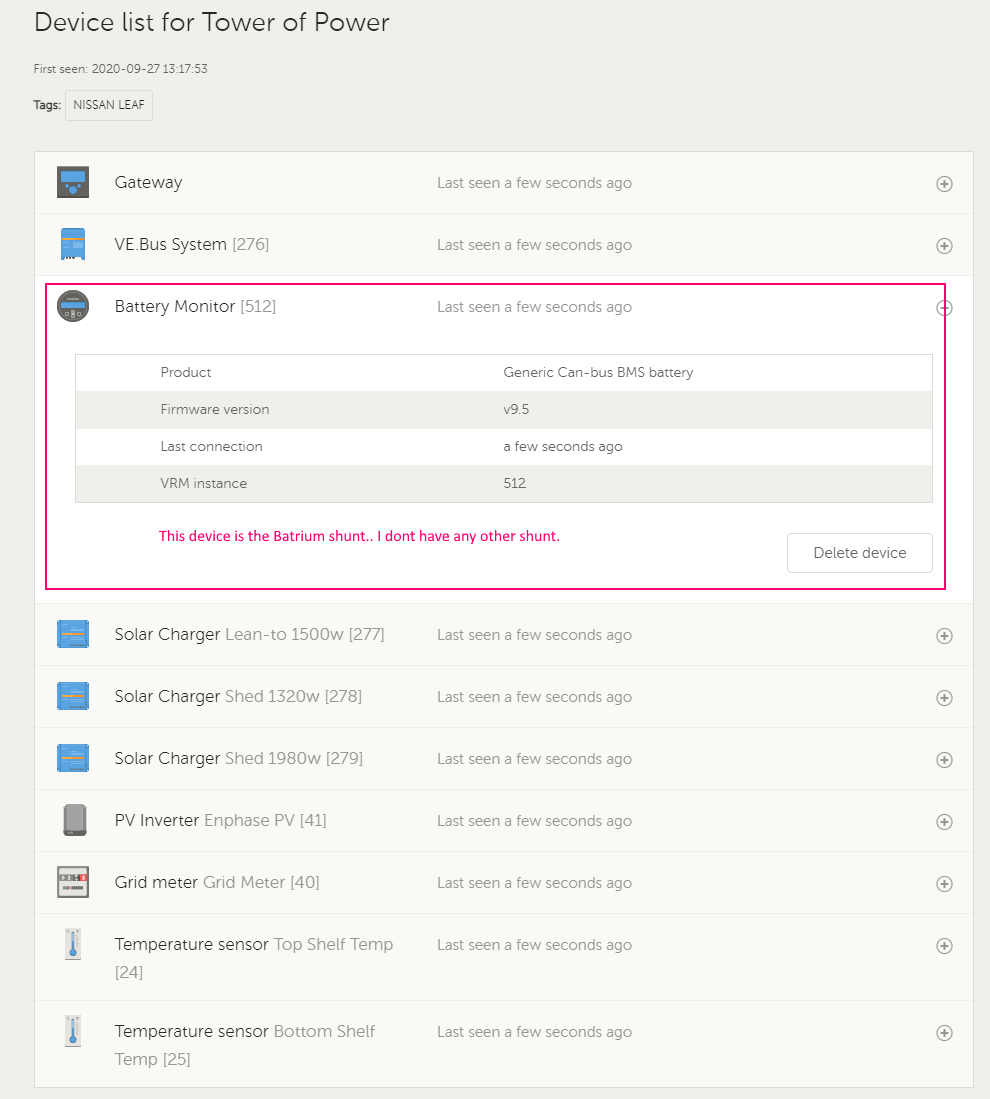
Q1. When doing a full DVCC Victron integration Do I require the DIYBMS Shunt, or can the DIYBMS grab the data from the Victron Shunt? Another way of asking is can either shunt be used?
Q2. What are the appropriate Victron DVCC Settings when using this BMS? (SVS on/off, etc)
Feature Request: I know Stuart was after feedback on the Victron integration and one thing the Batrium lacks is variable charge rate charging (based on say SOC or Battery Voltage.
When I have full sun, I can charge at 150+ amps - Which is fine when the cells are at 4v, but as we approach 4.1, the charge rate needs to be throttled back - to avoid some cells going to high.
The RECBMS has published their algorithm for this - And it would be ideal if the DIYBMS could do the same:
Battery Pack’s Charging Algorithm (from their instruction manual):
The communication between the REC BMS and the Victron CCGX is established through the CAN bus. All the parameters that control the charging/discharging behavior are calculated by the BMS and
transmitted to the CCGX unit in every measurement cycle.
The charging current is controlled by the Maximum charging current parameter. It’s calculated as
Charge Coefficient CHAC x Battery capacity CAPA. The parameter has an upper limit which is defined
as Maximum Charging current per device MAXC x number of inverter devices SISN.
When the highest cell reaches the Balance start voltage settings, charging current starts to ramp down to 1.1 A x Number of Devices until the last cell rises to the End of Charge Voltage. At that point the Maximum charging voltage allowed is set to Number of cells x (End of Charge Voltage per cell – 0.2 x end of charge hysteresis per cell). End of Charge SOC hysteresis and End of charge cell voltage hysteresis is set to prevent unwanted switching. SOC is calibrated to 100 % and Power LED lights ON 100 % Charge optocoupler is turned off. Charging is stopped in case of systems errors (See System Errors indication chapter). SOC is calibrated to 96 % when the maximum open circuit cell voltage rises above the 0.502 x (Balance start voltage + balance end voltage), minimum open circuit voltage above balance start voltage and system is in charge regime.
There is also a discharge algorithm, however, this is less important.
The manual is located here if anyone is interested: https://www.rec-bms.com/datasheet/UserManual_REC_Victron_BMS.pdf
Great work Stuart - I joined your Patreon a while back and am monitoring the progress. I have added the PCBs to the cart in JLPCB a few times, but I’m worried that I will be unable to source parts… I will need to bite the bullet at some point and just place the order.
Thanks Again!